What's new
Pinball info

Register a free account today to become a member! Once signed in, you'll be able to participate on this site by adding your own topics and posts, as well as connect with other members through your own private inbox!

Complete Terminator 2 Restoration

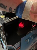
When I see that blinking LED on the MPU board I feel so less stressed.

Great job. :D

Also you passed the 'smoke test' :D
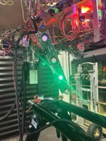
It’s was all going to plan on Friday night until I fitted the PinSound board and Colour dmd though 🤔. It ended up being a late one in the end.
 
Last edited:
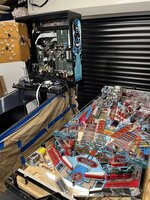
After the first successful test last Friday, I thought Id carry on and hook up the playfield.
I didn’t want to install the playfield into the cabinet only to have to take it again again if there was a problem, so I moved the rotisserie so that the playfield could be next to the cabinet.
CC24D50E-C39F-4562-A0F8-C505DFC7C45D.jpeg
This was the part I was most concerned about, so I checked all the wiring again to make sure it was all good.
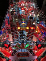
I did notice that the leaf switch on the upkicker for the T-800 head was not adjusted correctly so I quickly did that and switched it on.

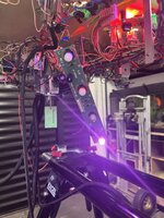
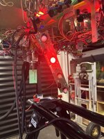
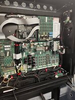
Everything seemed to turn on and there was no smoke billowing out from any boards. Nothing immediately locked up when it was switched on as well. Overall I was well pleased 😀
D10E7016-E3FE-48AA-A739-E9E06E4C7EDE.jpeg478AFAF2-8D0E-4E1F-8847-B9088069E752.jpeg
 
Last edited:
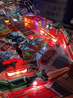
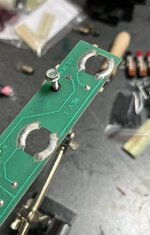
After closer inspection I did notice that some of the bulbs in the inserts were not coming on. I adjusted the legs on the leds and some did then come on, however most still didn’t.

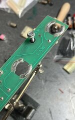
After some investigation, I decided to add some fresh solder to all the lamp boards as I suspected the twist lamp sockets were not getting good contact.
In hindsight I should have done that when I dismantled the original playfield and re-flowed the solder of all the lamp board connector pins as adding new solder did the trick.
2DD82970-0F9B-40FE-A59D-4912418EC114.jpeg3F53E47F-7F51-4963-A53C-F2DEADA8C5E1.jpeg
B567C6BB-9AC1-4C60-90EE-CC717A5E56EB.jpeg0C185F92-5F00-4955-BBB5-157CA7964A11.jpeg516F2C28-7316-4DF4-BDF0-FDED5B238ABE.jpeg
 
After closer inspection I did notice that some of the bulbs in the inserts were not coming on. I adjusted the legs on the leds and some did then come on, however most still didn’t.

After some investigation, I decided to add some fresh solder to all the lamp boards as I suspected the twist lamp sockets were not getting good contact.
In hindsight I should have done that when I dismantled the original playfield and re-flowed the solder of all the lamp board connector pins as adding new solder did the trick.
View attachment 168806View attachment 168807
View attachment 168801View attachment 168802View attachment 168803

Hah you made the exact same mistake I made with CFTBL!

TBH you end up doing so much stuff its easy to miss things. Some people use a list. I just burrow in my brain till I remember what I need to do :D

Out of interest where did you get the rotisserie? I may need one :/
 
Hah you made the exact same mistake I made with CFTBL!

TBH you end up doing so much stuff its easy to miss things. Some people use a list. I just burrow in my brain till I remember what I need to do :D

Out of interest where did you get the rotisserie? I may need one :/
Yeah I’ll just remember to do that on the next one.

I built my current rotisserie using the plans below. All in I think it cost me around £80 or so and it’s done the job. Though I have just ordered a purpose built one from the US.

 
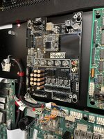
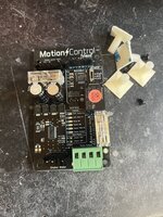
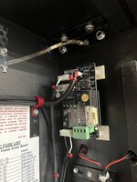
Now I knew everything was working, the last job I thought I’d do on the Friday was to install the PinSound board and motion control board, which should have been a 5 minute job.
C63A5EAD-FF28-48A0-94FE-6817E6D4D165.jpeg
08AF2876-630D-4BF0-A12E-9A49F3FB92EB.jpeg
6887579D-A269-4972-B9B8-9B584EC66AD7.jpeg4E5BCF26-A26C-46BF-9BBA-DF336EC04613.jpeg
Switched it back on and I get nothing. No GI, no solenoids, nothing came on. The mpu wouldn’t boot nor did the PinSound board. I had no clue as to why. I just couldn’t understand why it suddenly wouldn’t power on.
I tried reseating all the connectors but it still wouldn’t turn in. Checked the fuses and tested all the voltages on the driver board and they were good. I started to think it was a faulty PinSound board.
View attachment FullSizeRender.MOV
After a frustrating couple of hours I decided to go back to the beginning and back to basics as usually it’s something simple. I started by un-plugging all the ribbon cables and then only plugging in one at a time. My thinking was that way I could hopefully pin point what part to causing the mpu to not boot up.

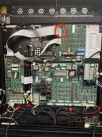
In end I finally identified that every time I plugged in the ribbon cable that went from the PinSound board to the DMD controller board the game would no longer boot.
I swapped in another dmd controller from another game to see if that worked and to confirm my suspicion, and it came back to life.

So I added some fresh solder to all the connector pins, plugged the ribbon cable back in and it finally booted again 😁
What was meant to be a couple of hours working on it after work at the end of the week turned into a marathon late night session.

By the time I got it working again it was gone 1.30am and I’d had enough for the night 😂

C4764406-85E2-498C-873C-5AD281A474EB.jpeg
 
Now I knew everything was working, the last job I thought I’d do on the Friday was to install the PinSound board and motion control board, which should have been a 5 minute job.
View attachment 168980
View attachment 168971
View attachment 168972View attachment 168973
Switched it back on and I get nothing. No GI, no solenoids, nothing came on. The mpu wouldn’t boot nor did the PinSound board. I had no clue as to why. I just couldn’t understand why it suddenly wouldn’t power on.
I tried reseating all the connectors but it still wouldn’t turn in. Checked the fuses and tested all the voltages on the driver board and they were good. I started to think it was a faulty PinSound board.
View attachment 168977
After a frustrating couple of hours I decided to go back to the beginning and back to basics as usually it’s something simple. I started by un-plugging all the ribbon cables and then only plugging in one at a time. My thinking was that way I could hopefully pin point what part to causing the mpu to not boot up.

In end I finally identified that every time I plugged in the ribbon cable that went from the PinSound board to the DMD controller board the game would no longer boot.
I swapped in another dmd controller from another game to see if that worked and to confirm my suspicion, and it came back to life.

So I added some fresh solder to all the connector pins, plugged the ribbon cable back in and it finally booted again 😁
What was meant to be a couple of hours working on it after work at the end of the week turned into a marathon late night session.

By the time I got it working again it was gone 1.30am and I’d had enough for the night 😂

View attachment 168974

Had this exact same issue when I installed new ribbon cables on both Shadow and CFTBL.

Cleaned and pins and several reseats later it all booted.


Is that an LED OCD board in the bottom right?
 
Got the Hunter Killer mod wired up and tested today. It works each time you start a new ball and when the canon is activated. The old one was just a wafer thin piece of plastic that did nothing.

If I’ve got time this evening I’ll run some tests on the switches and coils.
49880BC1-1C8D-4DA4-AF17-8C5058A831AC.png
 
Last edited:
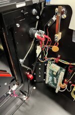
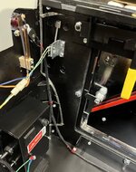
I did quick test on some of the switches and coils, including testing the cannon. I had to modify the wiring for the laser so that when this is activated the blue led mod I install in the cannon housing also comes on.

 
All switches are now fully adjusted. I also got the new dmd plugged in and tested. I think I’m at the stage where I can put the playfield back in the cabinet.
5BD48C61-5133-4EDE-9E2C-A00645258022.jpeg3D178173-7197-414A-AF88-346C20F2CFF2.jpeg
 
I would change those targets out for maybe transparent targets?
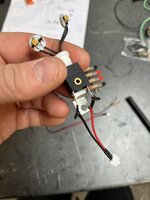
Yeah they look good. I’m at the stage now though where I’m so close to finishing I just wanna get done. Though I might add them to my next Marco order.

The only major job I have left to do is to finish fabricating the topper, but I’m waiting on this part for my welder to arrive.

My next project is sitting next to it screaming out to be started 😂
 
Last edited:
Going through my parts box last night, I came across an led speaker light kit which i completely forgot about.

Wasn’t a straight forward install as I had to modify the right side PinSound speaker mounting plate by enlarging the hole so the led could sit flush.

5D6F0BFB-590E-4C66-9E6F-C4E0BFFCF416.jpeg1295E6E1-0838-4068-BC88-94255DB5D13C.jpegE263B82D-0F61-4B71-9639-B9F6D6450063.jpeg6836ECCD-7711-4CD6-9D69-5C526FF9FDDA.jpeg
 
Been busy today with lots of cutting, welding, grinding and sanding trying to finish off the topper so it’s ready to be dropped off at the platers this week.

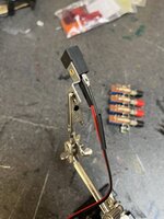
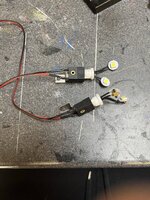
I did have some time last night, so made up a little lighting mod for the flipper buttons using some spare comet leds and lamp holders I had in the spares box.
7EC6F808-FF0F-4700-B18A-C9B50D8179A4.jpeg571DB876-42AF-4E6B-9A55-F0EC2A25E282.jpegB5B53B55-1EDB-4CD3-A090-43F13DF8D6F1.jpeg
I ended up tapping off the 5v from the start button to run them. Pleased with how they turned out.
3F95BC50-A027-4811-B1A2-FAFDBD1358B8.jpeg
08E9A718-5A22-4F4E-8BEE-9A78F81B98C9.jpeg
9F3AFDD8-71E5-4824-9E2C-AED04DE0CD06.jpeg
 
Last edited:
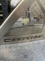
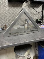
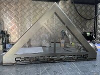
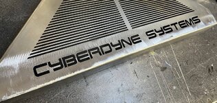
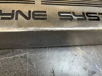
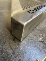
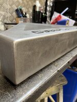
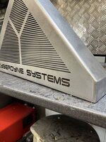
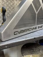
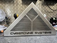
Over the weekend I’ve been working on a topper for my T2. I didn’t want it to look the same at the coin door, so went an alternate Cyberdyne Systems logo. The topper will be chromed and I’ll then add coloured acrylic and leds to light it up.

I would say it’s 90% nearly there but overall it’s come out better than I originally pictured it would.

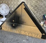
The first thing I did was to work out the basic shape/design and size. To help with this I made a rough questionable cardboard mock up 😂 to help me visualise what It could look like.
CC42FBD2-A8EC-42B9-9F29-4E4F50007F5B.jpeg
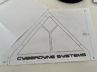
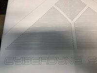
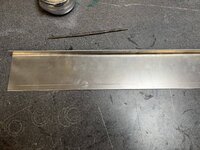
I then draw a basic design and sent it to the laser cutter to get it cut from a sheet 2mm mild steel.
B24A0BD8-A035-4D4D-A534-8EF5099D0725.jpeg
E7B6F5CD-C6BA-485F-BD9F-CBA990D4915B.jpeg
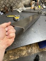
Once the design was cut the sides were then folded and ready for welding.
9D4009DE-D905-49CE-968A-B35742682644.jpeg62FFA899-2CF2-41C2-B6C0-57090822ACEF.jpeg5AD56A29-1C74-4BF6-B0D3-216CBD3F5D96.jpeg
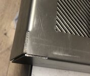
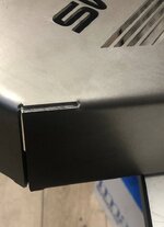
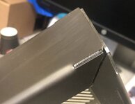
At this stage of the build the front of the topper was slightly warped, I think due to laser cutting the Cyberdyne font and it also having no base yet.
5C3A0BFA-E665-4A6E-A599-D7822B28483E.jpeg
So the next job was to try and correct the warping. To do this, I needed to fabricate a new base, again from a sheet of 2mm steel.
62D9B9EA-12BC-40D4-B502-A078040ECA34.jpeg
This was cut to size, with the corners notched out to help with the welding.
C9E7AB17-3EA7-45F7-BF22-4BD02E2F1E41.jpeg
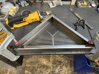
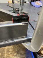
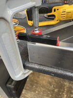
I clamped the topper down so that the sides were fully flat and held the base in place with magnets.
82988BFA-027D-4D56-BDBC-854B4F9B75D1.jpeg3B4E5CDB-BA57-4F20-AE75-D276E083858F.jpeg4BB80918-3D5D-4469-B91B-1EE7D668D16F.jpeg
As I tacked welded the base in place, I pushed the bottom of the topper down to correct the warping.
A63F55B4-57CE-478A-B67A-CE9239E02026.jpeg
This did the trick as the warping was no longer there 😀. Next job was to weld it up.
6838F5CF-0ABF-450C-99C8-6247A0F23497.jpeg
 
Last edited:
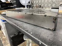
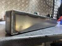
When it came to the welding, I had to be careful not to over heat the metal as I’d be back to square one with more warping and distortion.
But on the flip side, by not having enough heat, this can cause issues with the weld penetration and when it comes to grinding/sanding the welds down, the joints could crack.

So I decided to run beads of weld approximately 60mm in length, letting it cool, before doing another one.
09EA2406-A0AA-4B72-8F58-B6D9C469014A.jpeg8706741F-064C-4302-88C6-00727B34D760.jpeg938149C6-E448-4DE1-B1FC-1DD3E8E2CFBB.jpeg
The plan worked, there was zero distortion to the metal 👍🏻
 
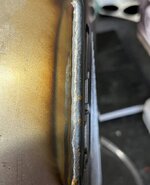
Once it had fully cooled I could start with the finishing of welds. I used a angle grinder with a sanding disc to remove most of the material.
28EE0A80-7469-4D3C-BE6A-91EC87F8E65E.jpegC2AD7218-2617-4B7F-8E3F-7CE735FBAE78.jpeg
5404B8D8-3D0B-43CC-B5C1-A374B67301F4.jpeg
This was then followed by lots of hand filing to round off all the edges and to get the rough shape I wanted.
9624D4AB-5AC7-41D7-8C99-68C50F5AD07D.jpeg
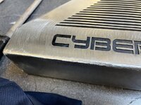
Once I was happy with the overall shape I sanded it all down starting with 60 grit sandpaper followed by 80 and 120 grit. This would refine and edges even more and gives a nicer curve.
D182FAB4-5E62-4908-B55B-585D79B4643C.jpeg83A04BCB-8A54-44F1-AA00-9C738BE534E4.jpegDB8EFE91-03D2-4702-A6B6-8AB86D02CBA4.jpegE58BBD36-29BC-4013-9225-87ABB0447B4E.jpeg
As it will be chrome plated, I need to make sure I remove any imperfections as if not these will show through the end result. So It will need another going over with a 240 grit sanding disc to finish it off.
 
Thanks mate. I did 2 years training in engineering/fabrication when I was 16………….but then stupidly I dropped out so I never finished 🤔🤯. But what I did learn I never forgot.

Christ! Imagine if you’d stuck with it. Could’ve had Millyard as your apprentice.
 
Wow, its really coming along.

That is just amazing work. Its becoming almost too good to play.
 
Back
Top Bottom