What's new
Pinball info

Register a free account today to become a member! Once signed in, you'll be able to participate on this site by adding your own topics and posts, as well as connect with other members through your own private inbox!

In Progress The Shadow

Have a good look at the coin door interlock switch, If that thinks the door is closed I don't think the service buttons will function.
What would I be looking for?
Also not sure if this relates but when I open the coin door it registers as a slam tilt…
 
its a little white button on the inside edge of the coin door (hinge side) it should pop out when you open the door, could be stuck?
 
Yes, but that would show an error message. Think there is something else amiss here. Have you checked closing the direct switches on the CPU board directly as described above?
 
Yes, but that would show an error message. Think there is something else amiss here. Have you checked closing the direct switches on the CPU board directly as described above?
When we say direct switches are we talking about the J205 plug to the CPU board, or the header pins for that plug on the CPU board itself?
 
The header pins. The way this works is that the digital 12V from the PDB (NOT to be confused with the unregulated 12V on J116-J118) are connected to the CPU and the switches via J205 on the CPU board. The CPU compares the voltage on the header pins against 5V - if it is higher, the switch is deemed open, if it is lower, the switch is deemed closed. This happens, when you close the switch which connects the header to ground (there is a "pull up resistor" in there to keep the fuse from blowing when the switch is closed). Ground is provided on pin 10, 6-9 are the direct switches on the coin door. These are called direct as there is no switch matrix involved, all of them are monitored directly. Most game switches are in a matrix, the corresponding column and row signals are on the connectors to the right of J205. We don't worry about those for the time being.
So remove J205, take a cable, connect one end to pin 10 (or the ground braid IF THAT IS CONNECTED PROPERLY!) and touch the other end of the cable to pin 6-9. This should emulate the switches on the door being closed. Report back :)...
I assume that connecting J3 to the coin board didn't get rid of the fuse error message? The other end should be on J212 on the CPU board, this is the connector above J205. What measuring equipment do you have?
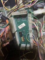
Following what you mean - before I go about shorting anything I assume I can use something like a paper clip? As far as measuring equipment I’ve got a multimeter.

I know it’s registering the coin door button presses as it brings up the message “To use buttons press enter to” but I can’t get further than that.

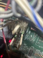
I’ve attached a photo of my coin door PCB to see if anyone can see something I’m missing:
image.jpg
 
You have a connector unplugged. Here is my shadow.
 

Attachments

  • 20220405_134103.jpg
    20220405_134103.jpg
    163.8 KB · Views: 31
On mine the ribbon connector at the left hand of the cpu board marked display is unpopulated....

To clarify, that 'Display' connector is a left-over from the alpha-numeric displays used on the earliest Wpc games (Funhouse, Bride of Pinbot and the other one).

That message about fuses appears if the door interface board in the cabinet isn't connected. Location 2,4 (Column 2, Row 4) of the switch matrix is 'Test Position, Always Closed" for every Wpc game. It's permanently wired, through a diode (D 2) on the door interface, so that J 3 being disconnected brings up the message. Seeing the 'switch' as open is taken as the 12v (Digital) being missing, and is programmed to display the message.

In your picture of the door interface, the second wire from the top of J3, Green-red, is switch Column 2. Row 4, for the 'always closed' connection, is White-yellow, Pin 6. It looks precarious in the connector.

Asia's picture shows J6 in use, but the pins on that are concerned with the electronic acceptor, if such a door is fitted*. The wires on that edge of the interface come from the door, while those on the opposite side come from the machine.


Also not sure if this relates but when I open the coin door it registers as a slam tilt…

Is the slam tilt switch (the lead-weighted switch in the top corner of the door) especially loose?. Loose enough to contact as the door opens. The thing is that the door switch makes contact when closed, so opening the door is opening the switch. Though these two aren't Direct switches, in any case. The Direct switch connections are shown on the interface board, next to J 5; SW 1 through 4 are the test buttons.

* the manual, being intended mainly for the domestic U.S. market, probably wouldn't mention J6. Games with an electronic acceptor fitted would've had a booklet included, with de##ls of the door, additional fittings on the interface, coin control switches, etc
 
Last edited:
To clarify, that 'Display' connector is a left-over from the alpha-numeric displays used on the earliest Wpc games.

That message about fuses appears if the door interface board in the cabinet isn't connected. Location 2,4 (Column 2, Row 4) of the switch matrix is 'Test Position, Always Closed" for every Wpc game. It's permanently wired, through a diode (D 2) on the door interface, so that being disconnected brings up the message. Seeing the 'switch' as open is taken as the 12v (Digital) being missing, and is programmed to display the message.

In your picture of the door interface, the second wire from the top of J3, Green-red, is switch Column 2. Row 4, for the 'always closed' connection, is White-yellow, Pin 6. It looks precarious in the connector.

Asia's picture shows J6 in use, but the pins on that are concerned with the electronic acceptor, if such a door is fitted. The wires on that edge of the interface come from the door, while those on the opposite side come from the machine.


Is the slam tilt switch (the lead-weighted switch in the top corner of the door) especially loose?. Loose enough to contact as the door opens. The thing is that the door switch makes contact when closed, so opening the door is opening the switch. Though these two aren't Direct switches, in any case
I’ll have another look at that suspect wire and see if that fixes it. Slam Tilt goes off whenever the coin door is opened or closed, so I suspect it’s a little loose.
 
Are you still getting the fuse error or is that gone since you connected J3 on the coin interface board?
 
Also, you can use a paper clip. Does the message say "Open coin door to use switches"? Photo of the message maybe.
 
I despise Bally manuals - says it’s not used in the manual but obviously there’s a connector somewhere. I can’t see it easily - where does J6 run from?
Sorry its not actually needed it just runs to the coin mechanism. Trying to be helpful before rushing out to the dentist should have looked a bit closer before posting.
 
Re. the door fitted; having finally thought to check the beginning of this thread, that door looks quite worn, and I doubt it's the machines original fitment. I haven't caught sight of the serial number label, but it ought to mention what sort of door the factory put in - such as 'The Shadow 2 Slot' or (if it's a u.k. machine) 'ECA', for electronic coin acceptor. This would account for the presence of J6 on the door interface, and the block of control switches. There's nothing particularly wrong with not having anything connected on J 6, though. It's simply for the additional stuff that comes with using an electronic acceptor, so if there isn't one, no problem.

Another thing about having a non-original door is the switches which are operated by the door opening or closing. With the two switches at the lower left corner, the door has a flange spot-welded on to contact them. An odd, or older door put on may well not have that, so alterations would be needed to actually use the machine; one of those switches is intended to cut out solenoid and flashbulb power with the door open. The other is the matrix switch 'Door Closed', with it pushed in trying the Test buttons inside the door displays the message "Open Door To Use Buttons". While opening the door often displays "Coin Door Open, Interlock (the other switch) Disables Playfield High Power". A couple of games need this switch closed to work properly - Dr. Who and Johnny Moronic get awkward unless the door is showing as closed.
 
Last edited:
All correct but shouldn't stop the buttons from working, we need @SpiderPin to update us on what is happening post connecting J3 on the coin board. That should have removed the fuse error. Next question is the direct switches, needs to be tested as described above - if there is an error message about using the switches or such we need to know it so we can progress from here.
 
So! Before I go shorting the pins (I went out to buy paper clips today) I thought I’d show the current state of Shadow. I double checked J3 and it’s pushed all the way in.
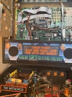
The machine turns on and shows this error:
image.jpg
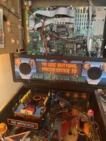
I then initiate a Slam Tilt by moving the coin door and get to the normal Shadow DMD animation. Then if I try to use the coin door buttons I get this message:
image.jpg
I can’t get any further than here.
I’m going to try shorting the pins now!
 
So I’ve tried shorting the J205 pins and the only thing I can get is that same “Use buttons press enter to” message. Whether that’s due to how the game is functioning or how poor I am at shorting pins remains to be seen.
 
Interesting. This looks like two messages garbled together actually. The „open coindoor to use buttons“ and press „enter to see report“ ones. LED1 on the PDB is on, correct? Pressing any of the buttons on the door does nothing, I assume?
 
There should be two white switches at the coindoor, mounted to the left side of the frame. Are those connected and functional, ie click when pressing?
 
Also, looking at the photo of the coin door board, are all plugs connected correctly on the right side? Look a bit offset to me.
 
Interesting. This looks like two messages garbled together actually. The „open coindoor to use buttons“ and press „enter to see report“ ones. LED1 on the PDB is on, correct? Pressing any of the buttons on the door does nothing, I assume?
No coin door button does anything - when you say LED 1 I can only find the +12V, LED7, LED 4 and LED6 on the PDB which are all lit.
 
image.jpg
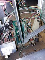
If there’s anyone with a Shadow can they confirm their J112 looks like this? Seems the cable is cut on the furthest to right but this might be factory.
 
There should be two white switches at the coindoor, mounted to the left side of the frame. Are those connected and functional, ie click when pressing?
There’s no audible click - the top one moves a tiny bit but not like a button and the lower one doesn’t move at all.
 
Last edited:
Also, looking at the photo of the coin door board, are all plugs connected correctly on the right side? Look a bit offset to me.
All the connectors on the right feel solid - the one for slam tilt on the bottom is a little shaky - there’s a bit of play moving left to right.
 
Don’t know if it’s too late but I have a spare gun used on a sega goldeneye, not sure if it’s any help but if it is drop me a pm.
 
Ok, but all are on the headers correctly, not offset to the left or right? If the white switches don’t pop out, they‘re broken. Should have about 1 cm of travel. Try pulling the plunger out a bit and report back please. Alternatively disconnect them.
 
Ok, but all are on the headers correctly, not offset to the left or right? If the white switches don’t pop out, they‘re broken. Should have about 1 cm of travel. Try pulling the plunger out a bit and report back please. Alternatively disconnect them.
So all the headers are in correctly. Top button is fine - goes in and out. Bottom doesn’t move. Not entirely sure how to disconnect them - tried to pull the red cabling out but it just seemed to bend. Is that button responsible for disabling high voltage to play field when the door is open?
EDIT - Nevermind, managed to pull off the connector. Is it worth leaving the top row on or should both rows or connectors for the buttons be removed?
 
Also as a slight aside if anyone is tearing down a Shadow would they be able to measure the wireform for the upper play field? Seeming like that will be a snag to source so considering making my own.
 
Should be spade connectors you can pull off (one is enough). Take pliers and pull the plunger out otherwise. Good chance you‘ll have to replace the switch anyway.
 
The upper of the two door switches, with 4 connectors on (and two unused pins), is the safety interlock. With the door open, it cuts the solenoid and flashbulb power. Games with this switch were supplied with a special clip, shaped to hold the switch in while the door was open. They were painted an unmissably bright yellow. I'd leave that one alone.

The lower switch is a matrix switch, which informs the processor when the door is shut. In the picture of your interface board, one of its connectors is poking out at an angle (Green-red wire, Switch Column 2). If it's jammed in, the test buttons wouldn't work as intended, but give the message 'open door to use buttons', half of which we seem to see.

Looking at your picture of J 112, the furthest right pin, No.5, should have a looped connection with the wire from pin 3. Two wires arrive from the transformer; one loops through pins 1 & 2, the other 3 & 5.
 
Last edited:
Back
Top Bottom