What's new
Pinball info

Register a free account today to become a member! Once signed in, you'll be able to participate on this site by adding your own topics and posts, as well as connect with other members through your own private inbox!

In Progress The Shadow

I use
 
Use in conjuction with some high grit sand paper to ensure a smooth finish


Then use a RAL code scanner app on your phone to find a close match to the grey.

Order some acrylic paint that matches the RAL code.

Apply , dry and then mylar over.

Or alternatively.

Sand to a smooth finish and buy a sanctum decal ontop.

 
Again though even that wood filler suffers from shrinkage. If you want a smooth perfect finish then you need to use resin as Ant suggests.
 
I use
That’s the filler I would use. It’s a resin based filler so is a lot tougher than the ready mixed stuff
 
Again though even that wood filler suffers from shrinkage. If you want a smooth perfect finish then you need to use resin as Ant suggests.
I think in this case resin won’t be any good as the damage isn’t very deep and sanding it down would be an issue.

A resin based filler will go on nicely and your be able to sand it smooth.
 
Cheers guys - going to get the filler @s00m linked. I've got a decal for the Sanctum so just need to put some filler down. Making some good progress...
 
I use
I've used this for repairing window and door frames - cures hard, very easy to sand/shape, and very stable because it's epoxy based.
 
Thanks for the help everyone - currently sanding down the filler so almost finished!

Taking a bit of a break to work on the pistol shooter and can’t work out how to get the grips off? I’ve removed the bolts so the pistol is in two halves but can’t work out how the grips are attached… if anyone knows I’d appreciate it! Manual is unfortunately no help and can’t find anything on the internet about it. Tried prying it off but doesn’t seem to work.
 
Last edited:
Looking gooooood!

Seem to remember the grips should just prize off once the bolts are removed, probs just beer and age holding them on.
 
And we’re back! With Shadow for a few weeks now so on to the next job - the upper play field!
Cosmetically the original was fine but it was missing the back drop targets - easy enough to find right? Wrong! Unobtanium.
Luckily a forum member here knew a guy that had parted out a Shadow and had an entire assembly going spare as well as a pistol shooter (have posted about this before) So I grabbed both and here we are.
The only missing part on the new PF is a solenoid but I’m just going to grab one from Phil. So what’s the plan?
I originally thought the path of least resistance would be to harvest and install the parts I need from the donor on to the current upper play field. However, whoever was working on the game before me has cut A LOT of the wires, so I think it’s easier to unplug the original one at the loom and simply install the donor play field. If anyone has any tips for this process, I’m all ears!
I’ve attached a photo of the two below - my new PF is on the bottom.
 

Attachments

  • 3E9144BF-6784-4C3E-9958-F2C932B5BEE9.jpeg
    3E9144BF-6784-4C3E-9958-F2C932B5BEE9.jpeg
    161.3 KB · Views: 21
Yeah no point messing around with cut wires, like you say just install the solenoid and plug the whole thing in, I removed mine once to clean up the sticky drop targets, don't remember it being difficult, although I would check the drops have smooth action now, may as well do any cleaning before you install,
 
From the pinball heaven repair guide a nice little tip for using a cable tie on the solenoid
Finally, the wires attaching to the solenoid (AE-25-1000) will break with years of left/right movement. You can either pull a few more inches out of the wiring loom to enable you to cut out the broken part, or cut out the damaged wire and use a terminal connecting block and attach new wire from the machine to the coil. Either way you should use a cable tie to firmly attach the wire around the body of the solenoid.

Other good tips too
 
Well... we're back again!
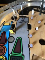
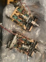
Haven't updated the thread as have only been doing everything one step at a time so updates wouldn't be particularly interesting. First, the good news: new Upper PF is installed and almost all the topside is back on. May not seem like much, but for me this was a good milestone. Game boots and I can get to test menu so I've got something to work with.

Bad news - most of the errors are still there. I posted them earlier but as a reminder to those at home:
Check Switch 51 Wall Target Down
Check Switch 55 Battle Drop Down
Time and Date not set
ERR. Mini PFF BAD Check switches / MTR
ERR. Magnet opto is not working
ERR. Battle kicker opto not working
ERR Wall TGT Bad check switch / coil
ERR Drop bank bad check switch / coil
ERR Bat drop bad check switch / coil

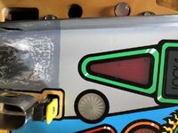
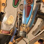
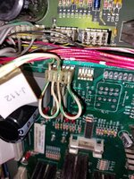
I think the majority of these will be due to my ropey (at best) J112 connector. At some point it's been cut:
1692347877911.png

Trouble is, I don't have a photo of the original configuration, or have any idea how to fix it. If anyone has done this before or has any ideas, I'm all ears!
 
Doesn't the manual have a chart showing what colour wire goes to which pin on which header? Might be a good place to start? I have a manual I can loan you if you PM me your details I'll post it out. Great game, good luck!
 
Doesn't the manual have a chart showing what colour wire goes to which pin on which header? Might be a good place to start? I have a manual I can loan you if you PM me your details I'll post it out. Great game, good luck!
Have been having a look and from what I can find in the manual (and from @Jay Walker) it looks like there should be loops from 1 to 2 and 3 to 5, but I think in mine these are in fine within the plug itself.
I'm going to look at how I can fix the cut wire now as that'll surely be the issue.
 
And that is +12V which powers the Optos - if shot the errors are explainable. F116 is fusing this so check that as well.
Depending on where in London you are I can crimp you a new connector.
 

Talk to @David retro about getting one?
 
LED7 is monitoring the 12V and seems to be on in your photo - that would mean you're having 12V - please measure at the other side of the board J116-118 between pin 2 and 3, you should have 12V there.
 
Back
Top Bottom