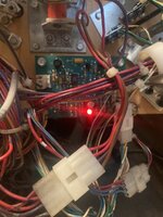
Even though J112 definitely needs repair it looks like you are getting 12v at the board as LED7 +12v is lit on your pic. So J112 is not the problem.Well... we're back again!
Haven't updated the thread as have only been doing everything one step at a time so updates wouldn't be particularly interesting. First, the good news: new Upper PF is installed and almost all the topside is back on. May not seem like much, but for me this was a good milestone. Game boots and I can get to test menu so I've got something to work with.
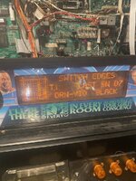
Bad news - most of the errors are still there. I posted them earlier but as a reminder to those at home:
Check Switch 51 Wall Target Down
Check Switch 55 Battle Drop Down
Time and Date not set
ERR. Mini PFF BAD Check switches / MTR
ERR. Magnet opto is not working
ERR. Battle kicker opto not working
ERR Wall TGT Bad check switch / coil
ERR Drop bank bad check switch / coil
ERR Bat drop bad check switch / coil
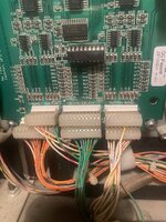
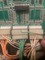
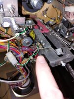
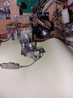
I think the majority of these will be due to my ropey (at best) J112 connector. At some point it's been cut:
View attachment 228752
Trouble is, I don't have a photo of the original configuration, or have any idea how to fix it. If anyone has done this before or has any ideas, I'm all ears!
Pinball info
You are using an out of date browser. It may not display this or other websites correctly.
You should upgrade or use an alternative browser.
You should upgrade or use an alternative browser.
In Progress The Shadow
- Thread starter SpiderPin
- Start date
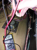
Beat me to it - your post came in as I was writingLED7 is monitoring the 12V and seems to be on in your photo - that would mean you're having 12V - please measure at the other side of the board J116-118 between pin 2 and 3, you should have 12V there.

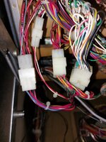
Pull j3 from battlefield opto board. What do you have between j3-4 and j3-5 on the connector

Good - as expected as you don't have errors showing on trough optos. I just wanted to check if +12v was getting to playfield.Upper PF board looks to be getting 12 V
Ignore me, read it upside down…Pull j3 from battlefield opto board. What do you have between j3-4 and j3-5 on the connector
Just to double check you mean testing the connector itself as opposed to the head on the board (which I assume has no power going through it anyway)Pull j3 from battlefield opto board. What do you have between j3-4 and j3-5 on the connector
J3-5 gets 2v
J4-5 gets 14V
Although that makes me think I’ve measured it wrong…
Sorry - I have confused. I thought you meant the Opto board near the flippers had its LED on. As your pic shows, you are getting +12v at the opto board as the LED is lit. You can check it is 12v if you want to but is should be OK.
J3-4 is pin 4 of connector J3 and has a black wire going to it
J3-5 is pin 5 of connector J3 and has a yellow grey wire going to it.
J3-4 is pin 4 of connector J3 and has a black wire going to it
J3-5 is pin 5 of connector J3 and has a yellow grey wire going to it.
There should be +12v between J3-4 and J3-5Sorry - I have confused. I thought you meant the Opto board near the flippers had its LED on. As your pic shows, you are getting +12v at the opto board as the LED is lit. You can check it is 12v if you want to but is should be OK.
J3-4 is pin 4 of connector J3 and has a black wire going to it
J3-5 is pin 5 of connector J3 and has a yellow grey wire going to it.
J3-5 reads 2V so I wonder if that’s causing some of the issue.There should be +12v between J3-4 and J3-5
J4-5 reads fine so I’m assuming it’s not my technique!
Yes, test between 4 and 5 on J3 connector with connector disconnected.Just to double check you mean testing the connector itself as opposed to the head on the board (which I assume has no power going through it anyway)
J3-5 gets 2v
J4-5 gets 14V
Although that makes me think I’ve measured it wrong…
OK so you have 12v supply at both opto boards. So j112 and curcuits and wiring all the way there is not the issue. It's either the boards or the switches or wiring between. I suspect boards as there are so many out.
Pic below of testing between j3-4 and j3-5 to check 12v
Pic below of testing between j3-4 and j3-5 to check 12v
Attachments
What did you mean by this? Is one of the boards shot?Yeah mine is absolutely shot so that would explain it.
It was originally in reference to J112 as it doesn’t look great but it seems to be functional.What did you mean by this? Is one of the boards shot?
When I get back I’m going to try and trace the opto wires and have a look at the boards and see if there’s anything obvious.
Just let me know if you need pics. I have left my shadow open.
Now we are out of the rabbit hole of +12v and determined it is OK, I went back to the original list much of the comments seems confusing but many are unrelated and its just a case of working through them one by one/ You can probably cross a few off that list quite quickly. I don't beleive you have a major issue with the optos - it's just small random individual switch errors.
1. Check Switch 51 Wall Target Down - check this in switch edges test - it's a microswitch not an opto mounted on the wall drop down target mechanism
2. Check Switch 55 Battle Drop Down - check this in switch edges test - a microswitch on underside of playfield on yellow battlefield drop down target mechanism
3. Time and Date not set - just set date and time on utilities menu adjustment 4 and this will go away.
4. ERR. Mini PFF BAD Check switches / MTR - probably related to 8. below
5. ERR. Magnet opto is not working - presumably this is switch 33 - the one I made up for you - check wiring correct and check to see that optos are aligned.
6. ERR. Battle kicker opto not working - I think they mean switch 36 which is controlled by the small upper opto board we have been discussing which only controls switch 36 - the opto in front of the battlefield kicker - check in switch edges and check to see that optos are aligned (its a long distance between them).
7. ERR Wall TGT Bad check switch / coil - Switch 51 again (or coil)
8. ERR Drop bank bad check switch / coil presumably switches 85-88 - check in switch edges test.
9. ERR Bat drop bad check switch / coil - presumably they mean battlefield drop target which is again switch 55
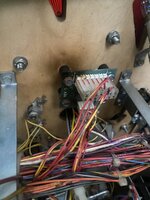
The burnt board is the diodes for switches 81,82,83 (unused) and 84. These are the targets on right side of mini battlefield. Just check these in switch edges test.
Now we are out of the rabbit hole of +12v and determined it is OK, I went back to the original list much of the comments seems confusing but many are unrelated and its just a case of working through them one by one/ You can probably cross a few off that list quite quickly. I don't beleive you have a major issue with the optos - it's just small random individual switch errors.
1. Check Switch 51 Wall Target Down - check this in switch edges test - it's a microswitch not an opto mounted on the wall drop down target mechanism
2. Check Switch 55 Battle Drop Down - check this in switch edges test - a microswitch on underside of playfield on yellow battlefield drop down target mechanism
3. Time and Date not set - just set date and time on utilities menu adjustment 4 and this will go away.
4. ERR. Mini PFF BAD Check switches / MTR - probably related to 8. below
5. ERR. Magnet opto is not working - presumably this is switch 33 - the one I made up for you - check wiring correct and check to see that optos are aligned.
6. ERR. Battle kicker opto not working - I think they mean switch 36 which is controlled by the small upper opto board we have been discussing which only controls switch 36 - the opto in front of the battlefield kicker - check in switch edges and check to see that optos are aligned (its a long distance between them).
7. ERR Wall TGT Bad check switch / coil - Switch 51 again (or coil)
8. ERR Drop bank bad check switch / coil presumably switches 85-88 - check in switch edges test.
9. ERR Bat drop bad check switch / coil - presumably they mean battlefield drop target which is again switch 55
The burnt board is the diodes for switches 81,82,83 (unused) and 84. These are the targets on right side of mini battlefield. Just check these in switch edges test.
Last edited:
Just let me know if you need pics. I have left my shadow open.
Now we are out of the rabbit hole of +12v and determined it is OK, I went back to the original list much of the comments seems confusing but many are unrelated and its just a case of working through them one by one/ You can probably cross a few off that list quite quickly. I don't beleive you have a major issue with the optos - it's just small random individual switch errors.
1. Check Switch 51 Wall Target Down - check this in switch edges test - it's a microswitch not an opto mounted on the wall drop down target mechanism
2. Check Switch 55 Battle Drop Down - check this in switch edges test - a microswitch on underside of playfield on yellow battlefield drop down target mechanism
3. Time and Date not set - just set date and time on utilities menu adjustment 4 and this will go away.
4. ERR. Mini PFF BAD Check switches / MTR - probably related to 8. below
5. ERR. Magnet opto is not working - presumably this is switch 33 - the one I made up for you - check wiring correct and check to see that optos are aligned.
6. ERR. Battle kicker opto not working - I think they mean switch 36 which is controlled by the small upper opto board we have been discussing which only controls switch 36 - the opto in front of the battlefield kicker - check in switch edges and check to see that optos are aligned (its a long distance between them).
7. ERR Wall TGT Bad check switch / coil - Switch 51 again (or coil)
8. ERR Drop bank bad check switch / coil presumably switches 85-88 - check in switch edges test.
9. ERR Bat drop bad check switch / coil - presumably they mean battlefield drop target which is again switch 55
The burnt board is the diodes for switches 81,82,83 (unused) and 84. These are the targets on right side of mini battlefield. Just check these in switch edges test.
Thank you so much for this - you’ve been a great help. Going to work through these in the next few days and I’ll see where I stand. Disassembled and cleaned the wall switch but no dice so wondering if I’m going to replace it as switches aren’t too expensive!
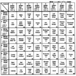
It could be the switch or the diode or the wiring to it. Check continuity with dmm between this and other switches on same row and same column, diode and whether switch itself operates. It could easily be as simple as a broken wire. Given that you have 2 switches out on column 5 I would be checking continuity on the column 5 wire first that loops around all the switches on column 5.
Column 5 has a green and black wire that loops around the switches on that column.
Pinball Lamp or Switch Matrix Troubleshooting -
Your pinball switch matrix acting up - Multiple switches turning on when only one should - Hit one switch and four go off? This is how to fix it.
 homepinballrepair.com
You may find this useful.
Thanks for this - great resource I've been working through.Pinball Lamp or Switch Matrix Troubleshooting -
Your pinball switch matrix acting up - Multiple switches turning on when only one should - Hit one switch and four go off? This is how to fix it.
You may find this useful.
Very few of the switches on the top side of the play field actually register. Only good switches are inside the cab pretty much.
Turning my attention to the CPU board - but it’s a new PinLED board so suspect it’ll be okay.
Turning my attention to the CPU board - but it’s a new PinLED board so suspect it’ll be okay.
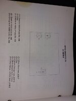
Hmmmm. Few things. On the CPU I’ve got connectors for both J206(s) listed in the manual despite the manual claiming they’re not used. The ones I have are also either empty or have one cable. Odd.
I also have a spare green and orange wire, but from looking at the wiring diagrams I can’t work out what’s it’s for. I already have J207-3 in the connector, so where does this go? The plot thickens.
I also have a spare green and orange wire, but from looking at the wiring diagrams I can’t work out what’s it’s for. I already have J207-3 in the connector, so where does this go? The plot thickens.