Pinball info
You are using an out of date browser. It may not display this or other websites correctly.
You should upgrade or use an alternative browser.
You should upgrade or use an alternative browser.
In Progress The Shadow
- Thread starter SpiderPin
- Start date
No Probs,Shows how reliable the manuals are. @kev a Thanks for looking, have to do a Shadow next week")
Guessing it was a change once they hit the production line and never updated the manual, if anyone needs any pics to confirm anything give me a shout.
I believe I have - for DMD driver it’s a new Rottendog board so I think the fuses should be OK. I’ve attached photos of the DMD wiring and the driver board which I think matches the manual, but if you notice anything let me know!First thing to do is getting the DMD to work. Have you connected all the connectors from the grey harness? Also, power from the DMD to the DMD board? All fuses ok? GI is mostly controlled by Triacs on the driver board, easier to debug once you can get into tests.

Attachments
I’ve added J208 but need to fix the actual plug of J206 - shouldn’t be related to GI should it?Its strange how the manual shows both those additional connectors as unpopulated, if it helps I can get some closer pics of wiring colours.
I can't say 100% the additional connectors are supposed to be like that, but mine works fine, and the previous owner hadn't removed the backglass since it was brought refurbished from PH in the late 00s (hence the batteries)
Edit:
Just done some digging online, seems its normal for J206 and 208 to be populated with one wire each, apparently they are run separately to the others as they are for the left diverter switch, which is mounted inside the cab and not on the playfield like the rest of the switches.
Nah not related, its just the switch for the left phurba diverter.I’ve added J208 but need to fix the actual plug of J206 - shouldn’t be related to GI should it?
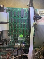
When you say Pin 1 is that on the DMD controller or DMD itself plug?Can‘t really see if pin 1 is correct, red stripe on the flat cable should go to the side of the connector marked pin 1. If that‘s the case I‘d check voltages on the DMD - careful up to 190V there!
Also how would I check DMD voltage - 190V has me a little nervous as I’m somewhat of a novice when it comes to electrics…
I’m thinking it might just be worth going for a new DMD if everything outside of it is working as electrics are not something to mess with for an idiot like me!Can‘t really see if pin 1 is correct, red stripe on the flat cable should go to the side of the connector marked pin 1. If that‘s the case I‘d check voltages on the DMD - careful up to 190V there!
Check ribbon cable before taking that step. You can always test the DMD in another machine first too.I’m thinking it might just be worth going for a new DMD if everything outside of it is working
Will do - ribbon cable is brand new so I’d be surprised but I have the original so will try that as well.Check ribbon cable before taking that step. You can always test the DMD in another machine first too.
The only other machine I have is a Stern High Roller Casino, I think the DMD would work in Shadow but I’m not entirely sure how.
Important thing is that the red cable on the flat link is on the same pin both sides. The connector on the board has a little „1“ silkscreened to the board on one end. Have a look if the red cable on the flat aligns with that in the DMD side and then make sure it is the same on the DMD board.
Had a look and the plugs and both the 1s are matching I believe - is it not impossible to get it wrong as the key is in a certain place?Important thing is that the red cable on the flat link is on the same pin both sides. The connector on the board has a little „1“ silkscreened to the board on one end. Have a look if the red cable on the flat aligns with that in the DMD side and then make sure it is the same on the DMD board.
I’ve put better photos of the plugs to see if there’s something I’m missing


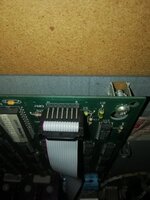
also check these ribbon cables, I'm not familiar with Rottendog boards so It could be correct, but it would be a bit unusual for pin one to be on the top on one connector and flipped over on an adjacent connector.
They tend to oriented in the same way....
Also check the other end of the cables are correct.


They tend to oriented in the same way....
Also check the other end of the cables are correct.
Last edited:
THIS WAS IT!also check these ribbon cables, I'm not familiar with Rottendog boards so It could be correct, but it would be a bit unusual for pin one to be on the top on one connector and flipped over on an adjacent connector.
They tend to oriented in the same way....
Also check the other end of the cables are correct.
View attachment 165828
View attachment 165831
Cannot believe it was as simple as flipping a cable. GI is now on too.
Only trouble is - DMD now says this:

Also swapped the ribbon cables round so red matches 1 on the two cables on the right.
Double check all the other ends of the ribbon cables, I think your problem could be the flat cable going into the dmd its self, its a data cable, so if its wrong the data gets all mixed up and it displays gibberish, but defo check the other end of all those ribbon cables too.
Much better, hope you haven't damaged anything by having it reverse. As per @Asiapinball, check all flat cables are plugged in correctly and not offset in any direction. Looks like the DMD works in principle. Does the content on the DMD move or is it static?
Think I may have found another issue - I’m missing a ribbon cable on J204 of the CPU board - says it should go to A-1600 J1 if anyone knows where that is?
I’ve seen little bits on the DMD move but it’s largely the same as pictured.
I’ve seen little bits on the DMD move but it’s largely the same as pictured.
I’ve had a look and they all seem fine. I tested with both the new and old cable and still have the same scrambled DMD.Double check all the other ends of the ribbon cables, I think your problem could be the flat cable going into the dmd its self, its a data cable, so if its wrong the data gets all mixed up and it displays gibberish, but defo check the other end of all those ribbon cables too.
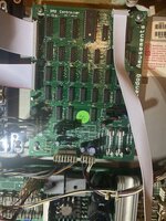
Any chance you could get a high-ish res pic of all the boards in the backbox? we might be able to spot something amiss.


Only thing I know needs fixing is the spare slot on the CPU - wire came out of the plug so I need to work out how to put that back in…
Attachments
Not seeing anything obvious.
Unfortunately on the PIN-LED site they don't go into detail but have the dip switches on the cpu board been set as per the manual?
Unfortunately on the PIN-LED site they don't go into detail but have the dip switches on the cpu board been set as per the manual?
Think the flat cable to the display board actually belongs on the connector on the left. Says Display on it, it is on extended IO. But not sure about that, never have used one of those.
Hmmm, probably not, seems they have the same header J-xxx designations and nothing mentioned in the manual.
Hmmm, probably not, seems they have the same header J-xxx designations and nothing mentioned in the manual.
Last edited:
Not entirely sure what you mean? In the manual J201 says to go to J602, and J204 to A-16100 J1 whatever that means.Think the flat cable to the display board actually belongs on the connector on the left. Says Display on it, it is on extended IO. But not sure about that, never have used one of those.
Hmmm, probably not, seems they have the same header J-xxx designations and nothing mentioned in the manual.

Interesting - says it should be on the manual but if yours works…On mine the ribbon connector at the left hand of the cpu board marked display is unpopulated....
View attachment 165840
Not sure what could be causing the DMD fault in that case…
Agreed, we have kind of ruled out the simple stuff.
I could be wrong here, but you don't have attract mode, a start up ding etc? I'm not sure the CPU is getting as far as fully booting.
Just to rule it out I think its worth checking the dip switches on the CPU board, even if they were set previously they could be knocked.
The set by the large battery on the CPU board seem to be the most important and 1/4/7 need to be in the 'on' position according to the PinLed manual.
Last edited:
Here’s my current settings that I believe matches the manual - still no attract or any GI or inserts.Agreed, we have kind of ruled out the simple stuff.
I could be wrong here, but you don't have attract mode, a start up ding etc? I'm not sure the CPU is getting as far as fully booting.
Just to rule it out I think its worth checking the dip switches on the CPU board, even if they were set previously they could be knocked.
The set by the large battery on the CPU board seem to be the most important and 1/4/7 need to be in the 'on' position according to the PinLed manual.
View attachment 165867
DMD still scrambled.

Slightly difficult to tell but
7 - ON
8 - OFF
9 - ON
10 - OFF