What's new
Pinball info

Register a free account today to become a member! Once signed in, you'll be able to participate on this site by adding your own topics and posts, as well as connect with other members through your own private inbox!

Complete Creature from the faded lagoon

Just to confirm, you are testing the fuses out of circuit, and using continuity test on a dmm?
Correct I pulled them out no joy.

They all seem fine.

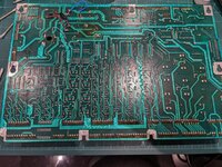
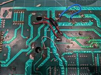
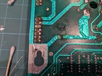
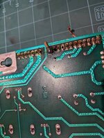
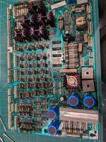
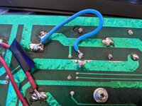
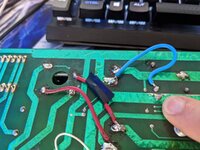
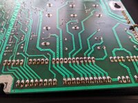
When I first pulled the board out after spotting the LEDs on the playfield were out I reflowed the capacitor on the far left of the board. I also used isopropyl alcohol on all the header pins as some were quite dirty.

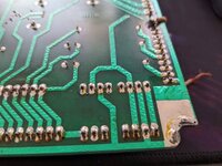
I then test continuity on all the caps initially having black and red in reverse and then corrected myself and got continuity beeps on all caps in the board.

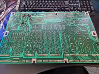
I then secured the board back into place.

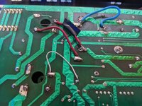
Powered it on and nothing. Then realised I had left a connector unplugged. J127 from memory. Plugged it in again. Still nothing.
 
Here's some pictures of the board.
 

Attachments

  • PXL_20220418_220431112.jpg
    PXL_20220418_220431112.jpg
    291.7 KB · Views: 25
  • PXL_20220418_220434163.jpg
    PXL_20220418_220434163.jpg
    254.8 KB · Views: 21
  • PXL_20220418_220439544.jpg
    PXL_20220418_220439544.jpg
    180 KB · Views: 24
  • PXL_20220418_220448305.jpg
    PXL_20220418_220448305.jpg
    139.2 KB · Views: 22
  • PXL_20220418_220505390.jpg
    PXL_20220418_220505390.jpg
    202.5 KB · Views: 21
  • PXL_20220418_220507905.jpg
    PXL_20220418_220507905.jpg
    174.2 KB · Views: 19
  • PXL_20220418_220518487.jpg
    PXL_20220418_220518487.jpg
    102 KB · Views: 19
  • PXL_20220418_220624201.jpg
    PXL_20220418_220624201.jpg
    198.2 KB · Views: 20
  • PXL_20220418_220627675.jpg
    PXL_20220418_220627675.jpg
    122.2 KB · Views: 23
Oh crap really?

Great not good...

Well, sortof. They will buzz initially but then not again after they take some of the power from the dmm. S8nce its a confusing result its not really worth doing. You're better off checking the circuit connections one leg at a time. Having said that, you won't have damaged anything doing the checks the way you did.

Back to basics. Check all the voltage inputs to the boards and make sure they are as expected.
Another thing to note is that at the request of the modder for HolomodSP and verifying in his manual he stated to change the capacitors from 15000uf 25v to 22000uf 25v.


Would this be the cause the problem? I'm reading everywhere you can change to a higher voltage but you shouldn't change the uf.

Scott
 
So @AlanJ or @myPinballs might wanna chime in on this one, but those massive caps on the power board are smoothing capacitors used to even out the full wave after bridge rectification. Upping their value should just provide extra capacitance, ie, extra smoothing in the case of high loads. I don't believe that would have any adverse effects.

I should point out that this won't apply to the use of ALL capacitors, only those used for this type of function.

However, having said that, why pinballSP isn't recommending the use of an external PSU to power his mod, rather than pretty extreme power board modifications (!) I do not know.
 
OK problem no.1 no power resolved.

The circuit breaker had tripped.. There I am unplugging the board, re-flowing etc, plugging back in. Nope zip try again and then I go to turn on The Shadow. No power... D'oh..

Will plug the board back in shortly and report back..

PXL_20220419_102127881.jpg
 
So @AlanJ or @myPinballs might wanna chime in on this one, but those massive caps on the power board are smoothing capacitors used to even out the full wave after bridge rectification. Upping their value should just provide extra capacitance, ie, extra smoothing in the case of high loads. I don't believe that would have any adverse effects.

I should point out that this won't apply to the use of ALL capacitors, only those used for this type of function.

However, having said that, why pinballSP isn't recommending the use of an external PSU to power his mod, rather than pretty extreme power board modifications (!) I do not know.
OK so the board is working again!

When it booted up I had everything again happy days but then 5 - 10 seconds later the playfield lights went out.

Any idea's what might be causing that. Power cycling the machine now and its still booting but without playfield lights (bar the GI which is fine).

Scott
No expert, but are there any shorts across those header pins? The flux and solder on each side look a bit ropey? What is that brown fly lead for? The added ground??
 
Again, uneducated troubleshooting tip..the gi connector that plugs into the headers, make sure it's connections are all crimped tight
 
Again, uneducated troubleshooting tip..the gi connector that plugs into the headers, make sure it's connections are all crimped tight
Not entirely sure was there when I got the machine. It looks like there was a burnt out pin (brown wire) and they ended up running a stitch wire from under the pin to back on top and then you have to splice the wires back together. I ran a continuity test on it and it 'seems fine' for what it is.

Which header is responsible for power for the playfield lights? Will have to check the manual and do some digging. The fact it comes on and then stop could mean a short or loose wire I suppose?
 
OK found it in the manual

Its J121 in the backbox for the GI.

I get something weird happen when I unplug it.

The GI goes out as predicted but the solenoids now successfully test fire when I turn the machine on.

I then go into test and fire off a solenoid and the GI flashes with it?!

So does that mean the board has a short between the solenoid header and the GI header?

Scott
I'd say you have a place to start. I think those headers should be looked at.
 
Right this is where I've got.

Taken the board out (again).

Gone through and checked continuity between pins and traced where I could to check continuity and all seem good. also checked between pins for a short, couldn't find anything.

Went through the board for the last hour or so cleaning with Isoprophyl and cotton buds clearing up all the flux and debris.

Couldn't see anything obvious causing my grief...
 

Attachments

  • PXL_20220419_133822862.jpg
    PXL_20220419_133822862.jpg
    120.5 KB · Views: 24
  • PXL_20220419_133835968.jpg
    PXL_20220419_133835968.jpg
    123.9 KB · Views: 25
  • PXL_20220419_141056828.jpg
    PXL_20220419_141056828.jpg
    240 KB · Views: 24
  • PXL_20220419_141105240.jpg
    PXL_20220419_141105240.jpg
    163.4 KB · Views: 21
  • PXL_20220419_141112045.jpg
    PXL_20220419_141112045.jpg
    127.7 KB · Views: 18
  • PXL_20220419_141116182.jpg
    PXL_20220419_141116182.jpg
    127 KB · Views: 19
  • PXL_20220419_141122801.jpg
    PXL_20220419_141122801.jpg
    152.9 KB · Views: 21
Last edited:
Right this is where I've got.

Taken the board out (again).

Gone through and checked continuity between pins and traced where I could to check continuity and all seem good. also checked between pins for a short, couldn't find anything.

Went through the board for the last hour or so cleaning with Isoprophyl and cotton buds clearing up all the flux and debris.

Couldn't see anything obvious causing my grief...
I had an issue with a board once, lots of repairs & hacks, sent it off to be tidied up - came back looking lovely, issue still remained. The board repairer then stated it MUST be the connectors then (as he had neatly replaced the headers) - and he was spot on. Definitely worth very closely inspecting connectors for brittle/burnt wires, mine were difficult to spot but were definitely the problem. Just a thought 👍
 
So still trying to sort out the Driver board but at least all the stuff has arrived.


PXL_20220419_171132235.jpg

PXL_20220419_171135790 (1).jpg

PXL_20220419_171137521.jpg
 
Phil Docker is coming to the rescue (I hope) to figure out what's wrong with the board.

Meanwhile I made some progress on the playfield and began some re-assembly.
PXL_20220419_181921248.jpg

PXL_20220419_215700984.jpg

PXL_20220419_215704218.jpg
 
In preperation for the LCD lagoon mod I needed to recap the WPC Driver Board. With much assistance from @Mfresh the replacement caps are now fitted.

Had a 'uh oh' moment when I got back and nothing powered on but then noticed one of the Caps wasn't fully flush with the PCB. Reflowed the Cap and reseated it. Added some more solder to cover the leg and voila the machine works again!

I'm confident doing my own caps now thanks to some invaluable knowledge share from @Mfresh.

Tomorrow the ramps should arrive and I can get really stuck in with finishing this machine!

View attachment 167375
Who’s telling you to recap a full driver board?? You really should not need to do this and changing caps on wpc board should only really be done if you’ve got a lot of board experience as you can rip the vias out easily. Also if changing caps, get the correct size ones. 30 years repair experience here and I only ever change isolated caps when there’s a specific fault in 1 power section. Anyway just my 2p

I’ve seen a few boards now ruined when someone tries to change all the caps for no good reason. Large power caps do not go bad very often! For example 5v reset faults are much more likely rectifier faults or 5v regulator faults or other smaller caps in my experience

It's in the modders guide a few posts back and he specifically messaged me to do it prior to installing the mod.

I did take the board to someone with soldering experience. Lesson learnt though the board was in ropey shape to start with the pads on one were already near gone.

Phil will give it a shot today to repair but I'll just buy a new board if I have to.
 
So Phil came and spent many hours trying to figure out whats wrong with the machine.

The board seems fine. We even had the insert lights going at one point and just like me he went to put the speaker panel back inside the machine and the lights went out.

Then the GI stopped working.

Then the DMD driver board was stopping the MPU board from booting

Then an Opto flipper caught fire

It was like a cascade effect.

There seems to be something wrong with the wiring. The caps seem good he checked the board rectifiers too again seemed good.

He thought it might be a data issue so tried another MPU board, no dice. No difference.

Its truly a puzzle even he was stumped as he's only had to walk away from a machine once not knowing whats wrong with it. This ones now the second.

He's offered to pick it up and take it back to his workshop which I'll likely take his kind offer on but in the mean time I'll try and see if I can figure out whats going on with the machine.

I've got the DMD driver board back on (looks like the connectors are just dirty on the board as the ribbons are brand new).

I got the GI working again, solenoids fire without issue.

Its just those damn playfield lights...

Its such a pain that they were working twice now but went out in the exact same manner. My gut feeling is the wiring but I can't see anything that would be causing it.

The clue could be when I put the DMD back in its pushing wires around in loom in the back box but simulating that kind of movement in the wires yields nothing.
 
I had one recenlty where I replaced the header pins but the solder didn't flow right through on one pin. The via must have be cracked or missing so it was coming on and off. I lifted the plastic on the header and soldered on the parts side too.
 
All new ramps fitted. That took a while...

One step closer?

PXL_20220421_133748359.jpg

PXL_20220421_133753490.jpg
 
  • Like
Reactions: Jib
Added on the flipper bats. Decided against using the pink car decal for now.

As the playfield is faded consistently throughout I'll just be happy enough having a 'rare' blue theme'd playfield.

Speaker grill also painted by the wife to bring back the white (it was basically grey before).

PXL_20220421_141818759.jpg


PXL_20220421_141844143.jpg
 
Once the driver board arrives tomorrow. I'll finish the install of the HolomodSP screen.

For now it'll remain unplugged wouldn't want this happening to it!

PXL_20220421_182411540.jpg
 
Back
Top Bottom