Pinball info
You are using an out of date browser. It may not display this or other websites correctly.
You should upgrade or use an alternative browser.
You should upgrade or use an alternative browser.
In Progress Laser Ball - Williams
- Thread starter James
- Start date

Hi @astyy
Still at stage 1, I was still getting black grime off of the machine even when I had put a lot of work into it so for me, that means I shouldn't move on to another stage just yet, there are areas I can see with a bit more work, will come up even better. I wasn't going to remove the rollovers, but a job worth doing etc. Is there a "proven" method of doing so with a walk through somewhere?
Still at stage 1, I was still getting black grime off of the machine even when I had put a lot of work into it so for me, that means I shouldn't move on to another stage just yet, there are areas I can see with a bit more work, will come up even better. I wasn't going to remove the rollovers, but a job worth doing etc. Is there a "proven" method of doing so with a walk through somewhere?
They're quite straight forward to remove...as ever this stuff is old so go gentle 


- remove one of the screws on the switch below and rotate it out the way
- from below push a drinking straw over the white knob on the end of the star, it's held by the teeth of the insert and the straw releases them
- wiggle the plastic star up and out using the straw from below
It's too blinking cold in my garage at the moment, I am thinking of getting it insulated, but to be honest, we are looking to move house so I don't really want to invest too much into and with the summer coming up, I may just have to hold out on it.
I am looking first at the right lower and upper flipper which are causing issues, the symptom being the right flipper will raise slowly if the button is held down, the top flipper doesn't do anything. Currently I am just pondering the schematic first, trying to get it right in my head before overlaying it onto what I can see on the play field.

On the right flipper, I should have the blue wire coming in from the power supply, bridging over the coil via the diode onto another unnamed switch, which appears to always be open, the end of stroke switch then returns to the center tab on the coil. The right side of the lower flipper should also have a blue and grey line to the right flipper button.

I have checked all of this over and apart from bad wiring, which I will completely re-wire. It looks like the wire from the other side of the diodeto unidentifiable open switch actually goes to the end of the bridged side via the diode on the upper flipper. Is that right?
I am looking first at the right lower and upper flipper which are causing issues, the symptom being the right flipper will raise slowly if the button is held down, the top flipper doesn't do anything. Currently I am just pondering the schematic first, trying to get it right in my head before overlaying it onto what I can see on the play field.
On the right flipper, I should have the blue wire coming in from the power supply, bridging over the coil via the diode onto another unnamed switch, which appears to always be open, the end of stroke switch then returns to the center tab on the coil. The right side of the lower flipper should also have a blue and grey line to the right flipper button.
I have checked all of this over and apart from bad wiring, which I will completely re-wire. It looks like the wire from the other side of the diodeto unidentifiable open switch actually goes to the end of the bridged side via the diode on the upper flipper. Is that right?
The lower right flipper has to activate first closing the switch to then activate the upper right flipper. Both the flippers also have an End Of Stroke (EOS) switch which is closed initially, this puts power through only part of the coil to give a powerful boost, but then as the flipper raises that EOS switch opens, and the power goes through the whole coil - so that the flipper can be held up for a period of time without burning the coil out.
The mystery switch is used to operate the upper flipper, once the main flipper has energised.
According to the diagram, the Blue 28v supply wire should arrive at the 'front' side of the upper flipper coil (with the banded end of the diode). then loop forward to the same terminal of the main flipper coil - I don't see where 'bridging over the diode' comes in. The End-of-Stroke switch shorts out the coils' secondary/hold winding until the switch opens. I'd disregard the additional switch until the main flipper is fixed.
To check the coil itself, it's okay to use a suitable length of wire to 'jump' the coil to ground. Connect the wire to a ground, such as the braid inside the cabinet, then carefully touch the other end to the tail end of the coil (plain end of the diode). This by-passes the button and relay contacts, so provided that the supply is okay, the coil should energise. The EoS switch may be burnt, so a further check is to momentarily ground the centre terminal, which is the junction of primary and secondary windings. This completes the circuit for the primary winding alone, so only touch the terminal briefly.
Here's an attempt to summarise;
Btw, the placement of the EoS switch for the upper flipper looks odd, the sensible place is shown by the screw holes alongside the coil
According to the diagram, the Blue 28v supply wire should arrive at the 'front' side of the upper flipper coil (with the banded end of the diode). then loop forward to the same terminal of the main flipper coil - I don't see where 'bridging over the diode' comes in. The End-of-Stroke switch shorts out the coils' secondary/hold winding until the switch opens. I'd disregard the additional switch until the main flipper is fixed.
To check the coil itself, it's okay to use a suitable length of wire to 'jump' the coil to ground. Connect the wire to a ground, such as the braid inside the cabinet, then carefully touch the other end to the tail end of the coil (plain end of the diode). This by-passes the button and relay contacts, so provided that the supply is okay, the coil should energise. The EoS switch may be burnt, so a further check is to momentarily ground the centre terminal, which is the junction of primary and secondary windings. This completes the circuit for the primary winding alone, so only touch the terminal briefly.
Here's an attempt to summarise;
- Assuming power supply is good, and flipper relay is energised
- Player presses flipper button, completing the ground circuit for the coil(s)
- Lower flipper pulls-in strongly, using its primary winding, with EoS switch closed
- EoS switch opens, bringing secondary winding into circuit and reducing the current flowing
- 2nd switch closes, repeating the process for the upper flipper
Btw, the placement of the EoS switch for the upper flipper looks odd, the sensible place is shown by the screw holes alongside the coil
Last edited:
Thanks @AlanJ and @Jay Walker the help is really really appreciated.
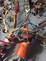
The mystery switch wiring as I see it on the coils is as follows. I have a jumper wire from the the anode side of the coil tab on the main coil to the anode side of the coil tab on the upper flipper. There isn't actually a mystery switch anywhere, just that jumper.
The mystery switch wiring as I see it on the coils is as follows. I have a jumper wire from the the anode side of the coil tab on the main coil to the anode side of the coil tab on the upper flipper. There isn't actually a mystery switch anywhere, just that jumper.
I find it easier to imagine the circuits without the diodes as they don't normally come into play, (they are just there to protect against reverse voltage that can be generated by the coil as the plunger moves back in, once the flipper button is released)
Okay, a bit of bodgery has taken place to eliminate the extra switch and have both flippers operate simultaneously. If whoever did it effectively joined the tail ends of the coils together then the two flipper units would be in parallel. Which might've worked, but isn't ideal. There should be a wire doing just that, though, in the original wiring (it would've run from the extra switch to the tail/anode end of the upper flipper coil). I'd remove that Red wire, and concentrate on the lower flipper first
Is the mystery switch an actual switch somewhere on the back of the play field I should be looking for then?
I will look to wire up the lower flipper correctly over the weekend and see if I can get it working right.
I will look to wire up the lower flipper correctly over the weekend and see if I can get it working right.
Yes, some wowser must've removed it from the lower flipper. The lower flippers' EoS switch should have the 2nd switch stacked onto it, with an additional 'pusher' flange (or a plastic nub attached to the longer blade) to close the 2nd switch as part of its own travel when it opens.
The reason why the 2nd flipper fires after the first one has fired is to stagger the power drain so they both flip powerfully. It will work if they both fire together but may reduce flipper effectiveness, and more likely to blow a fuse.
I’m guessing this was what the extended block bit here was for then, mystery switch area. Will order one from @pinballmania with the rest of my order then to get this resolved. I am thinking it is this one.... https://pinparts.co.uk/products/a10-45-normally-open-tungsten-repaeater-eos-switch

Last edited:
Something like this:
https://pinparts.co.uk/products/a10-45-normally-open-tungsten-repaeater-eos-switch
https://pinparts.co.uk/products/a10-45-normally-open-tungsten-repaeater-eos-switch
What he says ^ goes here:

Another day, another dollar, another problem. Still, looks better now even if it is a problem child.

So I managed to find a normally open switch in a box of bits a forum member sent me from his Gorgar and wired in the flippers, after replacing the bats initially, as they, well, you can see...

I rewired the pop bumper that was taken off by the last owner, (with Gorgar replacement) red power to banded side of diode.
Replaced the missing drop target solenoid with the Gorgar one, getting rid of the old mechano hack.

Wired the flippers as discussed.


Switched it on to see what happened... and all of these solenoids locked on.

Joy...
So I managed to find a normally open switch in a box of bits a forum member sent me from his Gorgar and wired in the flippers, after replacing the bats initially, as they, well, you can see...
I rewired the pop bumper that was taken off by the last owner, (with Gorgar replacement) red power to banded side of diode.
Replaced the missing drop target solenoid with the Gorgar one, getting rid of the old mechano hack.
Wired the flippers as discussed.
Switched it on to see what happened... and all of these solenoids locked on.
Joy...
Attachments
You've made quite a few changes there. Which one has caused the issue?
You've made quite a few changes there. Which one has caused the issue?
I don't know

so the lesson is?
Sent from my iPhone using Tapatalk
Don't try something you don't know enough about?
Don't try something you don't know enough about?
no i was meaning do one fix and test it then do the next etc
Sent from my iPhone using Tapatalk
I will have a go at taking everything back tomorrow, getting another look at it.
If they are locking on again now, hopefully I haven't fried anything - and if I have, I will fix it, this is now not only a labour of love, it is now a mission.
If they are locking on again now, hopefully I haven't fried anything - and if I have, I will fix it, this is now not only a labour of love, it is now a mission.
you have some good pointers from @Moonraker so go for those first. again take one change out at a time
Sent from my iPhone using Tapatalk
Sent from my iPhone using Tapatalk
