Pinball info
You are using an out of date browser. It may not display this or other websites correctly.
You should upgrade or use an alternative browser.
You should upgrade or use an alternative browser.
In Progress Laser Ball - Williams
- Thread starter James
- Start date
Re. the IC sockets; if they're still the original-fitment 'Scanbe' items, I'd change them regardless of whether they're affected or not. Contact is made to the sides of the chip legs, rather than the larger 'faces'.
Looking closely at the Cpu, what's happened with socketing the Cmos Ram?. Williams didn't use a socket, and the one fitted seems to have one more pair of connections than the chip has pins
Looking closely at the Cpu, what's happened with socketing the Cmos Ram?. Williams didn't use a socket, and the one fitted seems to have one more pair of connections than the chip has pins
Evening all - well I hope that I have done this right, given the board a real clean, with bleach and then cleaned that all off.
So - to me I think I will need to run a total of 4 traces on the underside of the board,I also need to purchase a few components, namely IC25, C67, C65 and C16 - although I need to find what they actually are too...
Looking at the schematic, I think I need 4 jumper wires based on my latest findings (based on the schematic and highlighted on my image)
IC22 left pin 1 (top to bottom) to IC21 left pin 1.
IC22 Right 7 to IC21 Right 7
IC22 Right 11 to IC21 Right 11
IC26 top 4 (L to R) to blank hole, not sure if this is needed to be honest.


To be honest, I am a little worried I might be doing all of this and get no where, having a bit of a crisis of confidence and thinking maybe I should just send it off to a pro... I nearly have enough put by for a DMD machine too though, and don't really want to eat too much into that doing this up spending money on the pro's if I can get there myself in the end, I would LOVE to be able to have both pins working.. but I know that is probably being greedy.
Thanks to @carl lawrence for sending up some parts off of his old Gorgar machine, I have also had the playfield out to put in the pop bumper solenoid that was taken out and get ready to make sure all of this is sound, before (and once the MPU is back up and working) I clean it up to serviceable and usable status.


As always all, thanks for reading and any help you can offer is genuinely appreciated.
So - to me I think I will need to run a total of 4 traces on the underside of the board,I also need to purchase a few components, namely IC25, C67, C65 and C16 - although I need to find what they actually are too...
Looking at the schematic, I think I need 4 jumper wires based on my latest findings (based on the schematic and highlighted on my image)
IC22 left pin 1 (top to bottom) to IC21 left pin 1.
IC22 Right 7 to IC21 Right 7
IC22 Right 11 to IC21 Right 11
IC26 top 4 (L to R) to blank hole, not sure if this is needed to be honest.
To be honest, I am a little worried I might be doing all of this and get no where, having a bit of a crisis of confidence and thinking maybe I should just send it off to a pro... I nearly have enough put by for a DMD machine too though, and don't really want to eat too much into that doing this up spending money on the pro's if I can get there myself in the end, I would LOVE to be able to have both pins working.. but I know that is probably being greedy.
Thanks to @carl lawrence for sending up some parts off of his old Gorgar machine, I have also had the playfield out to put in the pop bumper solenoid that was taken out and get ready to make sure all of this is sound, before (and once the MPU is back up and working) I clean it up to serviceable and usable status.
As always all, thanks for reading and any help you can offer is genuinely appreciated.
Your heading in the right direction and without doubt this is the worst bit , I find, of board repair. Everything is laid bare and looks beyond repair.
In all honesty it does look ugly but not unsalvageable. Most of the missing and deformed pads are not required by the circuit they just help retain the IC sockets.
To repair the missing pads with circuit traces I make lassos out of wire and secure them in place using the socket leg and then solder in place.
Broken traces can be repaired by bridging the gaps by soldering wire over them.
If you don't feel up to it or you don't want to take the risk let me know and I will have a crack at it for you for free as I feel partly responsible for getting you to this low point and I love a challenge like this.
Evening all - well I hope that I have done this right, given the board a real clean, with bleach and then cleaned that all off.
So - to me I think I will need to run a total of 4 traces on the underside of the board,I also need to purchase a few components, namely IC25, C67, C65 and C16 - although I need to find what they actually are too...
Looking at the schematic, I think I need 4 jumper wires based on my latest findings (based on the schematic and highlighted on my image)
IC22 left pin 1 (top to bottom) to IC21 left pin 1.
IC22 Right 7 to IC21 Right 7
IC22 Right 11 to IC21 Right 11
IC26 top 4 (L to R) to blank hole, not sure if this is needed to be honest.
View attachment 57861
View attachment 57862
To be honest, I am a little worried I might be doing all of this and get no where, having a bit of a crisis of confidence and thinking maybe I should just send it off to a pro... I nearly have enough put by for a DMD machine too though, and don't really want to eat too much into that doing this up spending money on the pro's if I can get there myself in the end, I would LOVE to be able to have both pins working.. but I know that is probably being greedy.
Thanks to @carl lawrence for sending up some parts off of his old Gorgar machine, I have also had the playfield out to put in the pop bumper solenoid that was taken out and get ready to make sure all of this is sound, before (and once the MPU is back up and working) I clean it up to serviceable and usable status.
View attachment 57863
View attachment 57864
As always all, thanks for reading and any help you can offer is genuinely appreciated.
If you spend money on a pro, it’s still gonna look like a hacked board with battery damage and you won’t have the satisfaction of fixing it yourself (or the cash). It’s not like it’s a shiny new board that you want to keep looking mint.
In the long run you might get a new one by keeping an eye out on the usual websites and set up some eBay alerts. Worth dropping Andy at pinball mania a message to see if he can source one.
In the meantime, I’d feel more pride for bringing it back to life than guilt for butchering an already dead board.
Sounds like you have got enough knowledge and support on here, and if you really balls it up, Moonbus sounds like he’s ready to dig you out of the mud.
It’s your machine, but I’d just dig in, really take your time, get set up for it, (and if you need to get any new soldering kit, you can justify the spend) [emoji106]
Hi @Moonbus - thank you for your kind offer - I am going to give it a blast - what's the worst that can happen, as @edsr has said - it is about getting that satisfaction and I am getting some of that right now, it just seems quite a way away, along with the fact that I am not 100% sure this is even the problem, although would certainly point to being an issue that needs solving even if it isn't THE problem.
What wire do you use for making the jumpers and little lasso's - will head into Maplin again and get some (or Amazon) although I think Maplin for the IC chip and resistors - need to find a part list for these too... not on the Schematic I have.
What wire do you use for making the jumpers and little lasso's - will head into Maplin again and get some (or Amazon) although I think Maplin for the IC chip and resistors - need to find a part list for these too... not on the Schematic I have.
Keep going @Adajam4 - you are doing amazingly well, and you have kind offers of help above if the going gets really really tough. I am no electronics whizz but I have learnt to do the basics and the biggest thing I have learnt is: Take your time, don't rush, one thing at once. It's all logical, and you have a circuit diagram which is essential.
I have never done PCB repair before - until my much loved Miele Oven blew up just before Christmas:


Miele quoted me £1,650 to repair it and that wasn't even a firm guaranteed fix price!!!!! I fixed it myself for £6 worth of parts (2 new relays) and a few bits of copper wire to replace the burnt out PCB tracks & a couple hours time.
Admittedly, my fix didn't involve quite as many damaged tracks as yours - but it was all 240V stuff, so rather scary!! I took my time to trace back the circuits to figure out what the relays were connected to, and then tested out each item to ensure the problem wasn't elsewhere.
I'm enjoying seeing your progress.......
I have never done PCB repair before - until my much loved Miele Oven blew up just before Christmas:
Miele quoted me £1,650 to repair it and that wasn't even a firm guaranteed fix price!!!!! I fixed it myself for £6 worth of parts (2 new relays) and a few bits of copper wire to replace the burnt out PCB tracks & a couple hours time.
Admittedly, my fix didn't involve quite as many damaged tracks as yours - but it was all 240V stuff, so rather scary!! I took my time to trace back the circuits to figure out what the relays were connected to, and then tested out each item to ensure the problem wasn't elsewhere.
I'm enjoying seeing your progress.......
Cheers @AlanJ - feeling a lot better now and thinking over it a bit more I am getting more confident of the next steps, which is good. Even for a Miele that is a hell of a lot of money. I know they are top end, but that is top money and what a time for it to go!
Talking about confidence - I WAS NOT confident I could fix the Miele, so bought a brand new Indesit Oven just in case I didn't as I had 11 people round for Christmas Dinner!!! Needless to say I now have a brand new Oven sat in the Garage........
I am not 100% sure this is even the problem, although would certainly point to being an issue that needs solving even if it isn't THE problem.
It is a very large part of THE problem which is why everyone said you need to instigate a repair before going any further...
There are some small areas that I'd clean (usuing very fine sandpaper or equivalent) the tracks further until all the really dull grey has turned shiny silver or copper as solder will not adhere to the dull grey stuff.
Good job.
The jumper wires and lassos, I use a solid core wire with a diameter slightly less then the width of the trace I'm trying to repair. Anything thicker risks interfering with neighbouring traces. I mainly salvage from old coils, network cable, phone lines etc.
IC sockets, get open ones with good access in the middle. Enough space that you can get to the pins from both sides of the board with the soldering iron. In these situations it is the only way to be sure you have done a good job.
Good luck and keep fighting.
I use this type, gives great access but you need to be more carefull with alignment. You can cut them to required length.
https://www.maplin.co.uk/p/modular-connector-32-socket-strip-dc17t
https://www.maplin.co.uk/p/modular-connector-32-socket-strip-dc17t
I use this type, gives great access but you need to be more carefull with alignment. You can cut them to required length.
https://www.maplin.co.uk/p/modular-connector-32-socket-strip-dc17t
These are what I have bought - as I said struggled to seat the chip when trying it out... might just be me though, getting that alignment right.
Am I being quite stupid in only being able to find a system 7 parts list online, even though I have the schematic, cannot find a parts list...
The manual on ipdb has them - it's the bill of material. eg. MPU parts are shown on page 10 of 40 in the pdf:
http://mirror2.ipdb.org/files/1413/Williams_1979_Lazer_Ball_Full_Manual.pdf
The manual on ipdb has them - it's the bill of material. eg. MPU parts are shown on page 10 of 40 in the pdf:
http://mirror2.ipdb.org/files/1413/Williams_1979_Lazer_Ball_Full_Manual.pdf
This has an upgraded system 4 board in it though, so need to find correct resistors and chip from system 4 board I assumed...
Ok so use system 4 schematics instead...
http://mirror2.ipdb.org/files/2372/Williams_1979_Stellar_Wars_Schematics_paginated.pdf
http://mirror2.ipdb.org/files/2372/Williams_1979_Stellar_Wars_Schematics_paginated.pdf
Ok so use system 4 schematics instead...
http://mirror2.ipdb.org/files/2372/Williams_1979_Stellar_Wars_Schematics_paginated.pdf
A-HA (not the band)
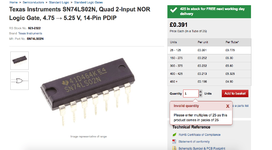
IC25 is listed as a quad input NOR Gate -7402 - Maplin has this https://www.maplin.co.uk/p/4001-cmos-logic-hcfhef-qx01b which is also a quad input NOR Gate, interchangeable?
IC25 is listed as a quad input NOR Gate -7402 - Maplin has this https://www.maplin.co.uk/p/4001-cmos-logic-hcfhef-qx01b which is also a quad input NOR Gate, interchangeable?
you’ll get a sn7402n or whatever the original part no you need from ebay or rs components
Sent from my iPhone using Tapatalk
OK Cool will setup an RS account then - need some fuses from then anyway")
just order and pay. don’t really need an account it creates it as you check out i think or just let’s you pay without an account.
Sent from my iPhone using Tapatalk
just order and pay. don’t really need an account it creates it as you check out i think or just let’s you pay without an account.
Sent from my iPhone using Tapatalk
Won't be buying 25 of them - eBay it is!
Won't be buying 25 of them - eBay it is!
they sell one.
Sent from my iPhone using Tapatalk
they sell one.
Sent from my iPhone using Tapatalk

but probably get one cheaper on ebay. rs do deliver fast though and often free
Sent from my iPhone using Tapatalk
OK so I have ordered the chip needed and capacitors from RS - I am now away with work for a couple of days, so will not be doing anything in the interim.
Managed to give it a good clean up and dust down as per @Moonraker 's advice, to bring it up to this. Whilst this looks a little dull, this is not bad in the flesh and gives some "shine" for the solder to adhere to.

I have then soldered in one of the IC lines, along with the jumpers, which I tinned first, it was fiddly and I am pretty confident I haven't bridged any pins here in doing so.

Managed to get the chip into the socket, but how much handling can these things take? I had to clean the pins off too, as these were disgusting and had a little acid on them (cleaned off now too) but has this destroyed the chip? If so, or as a precaution, should I get a new ROM set in?

I am feeling more confident I will get this somewhere now.... just going to take time and patience.
Managed to give it a good clean up and dust down as per @Moonraker 's advice, to bring it up to this. Whilst this looks a little dull, this is not bad in the flesh and gives some "shine" for the solder to adhere to.
I have then soldered in one of the IC lines, along with the jumpers, which I tinned first, it was fiddly and I am pretty confident I haven't bridged any pins here in doing so.
Managed to get the chip into the socket, but how much handling can these things take? I had to clean the pins off too, as these were disgusting and had a little acid on them (cleaned off now too) but has this destroyed the chip? If so, or as a precaution, should I get a new ROM set in?
I am feeling more confident I will get this somewhere now.... just going to take time and patience.
Good work! [emoji106]
As you’ve got large exposed areas of live board it might be worth looking at a conformal pen to reduce the risk of shorts, arcing etc. It can really tidy up how a board looks - like a green tippex pen that re-insulates the exposed metal tracks. See top left of my power board.

https://rover.ebay.com/rover/0/0/0?mpre=https://www.ebay.co.uk/ulk/itm/322699676630
As you’ve got large exposed areas of live board it might be worth looking at a conformal pen to reduce the risk of shorts, arcing etc. It can really tidy up how a board looks - like a green tippex pen that re-insulates the exposed metal tracks. See top left of my power board.
https://rover.ebay.com/rover/0/0/0?mpre=https://www.ebay.co.uk/ulk/itm/322699676630
Managed to get the chip into the socket, but how much handling can these things take? I had to clean the pins off too, as these were disgusting and had a little acid on them (cleaned off now too) but has this destroyed the chip? If so, or as a precaution, should I get a new ROM set in?
For peace of mind a new ROM set would be best. If the legs were that bad then the sockets holding them are likely to be as well, so now might be a good time to replace them...
