What's new
Pinball info

Register a free account today to become a member! Once signed in, you'll be able to participate on this site by adding your own topics and posts, as well as connect with other members through your own private inbox!

In Progress Laser Ball - Williams

When I had my Gorgar the first time I powered it up ,I had to have the coin door open to get it in attract mode ,then after that it was fine ,was told later it was because we took the head off to transport it !

That wasn't right, it would've been due to the Cmos ram being corrupt, probably from battery problems. How were you supposed to transport it, anyway, when it didn't have a hinged backbox?

The caper with the door having to be open to boot in attract mode in this situation is what's lost by putting an L6 program on an L4 board - when closed, the switch prevents factory settings being installed

I'd have to check with the slightly risible Williams troubleshooting book (which assumes spare boards grew on trees), but I don't think the Cpu board will boot fully on its own, without the driver board attached. The PIA chips on the driver board are part of the Cpu architecture, AIR

I looked at this games' entry on the database ipdb.org yesterday, and saw a bulletin which mentioned the original-fitment Cpu for Laser Ball, Firepower and King Tut (a 'shuffle' game using this hardware) having two of the smaller 'transceiver' 8T28 chips replaced by simple pad-to-pad links
 
Last edited:
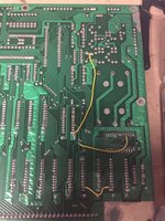
So yesterday I got the work bench power supply and tried to test the MPU without the driver board attached also, got the unit to power up and do the "flash to stable" LED run, which apparently means it booted ok and was looking for the driver board. I noticed some jumper wires on the back of the unit, which I cannot explain from any of the guides I have seen, so not sure what this mod has attempted to achieve. If it was working at some point, I am kind of hoping it will still be. I am going to take off the battery pack as there was some leakage on the pack and a little underneath, so will check any other damage in the area and remove, as well as change the 40 pins once I get a new one in.

IMG_5286 (1).jpg
 
Last edited:
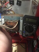
Think I have had my.. Uh Oh moment, the step down converter is shot.... can't get any continuity reading off of the primary or secondary side... Not sure how I was getting GI lighting though with it doing this.

image1(2).jpeg
 
Last edited:
If they all test out Ok, then next step would be to wire up the bridge rectifiers to the transformer and see if they produce a DC voltage
 
Would a continuity check not do this?

As you can tell, limited experience in this stuff lol
 
Oh sorry - it looked like you had meter on DCV - If you have it on continuity then that's looking for a short circuit basically.

On a transformer though you'd be checking for some sort of resistance (ohms) across two of the lugs if there is no power to it. Then with power to it, you'd be wanting to test for AC voltage
 
So getting no resistance (Ohms) set to 200 and no movement on the continuity is this knackered as pictured or am I still testing it wrong?
 
A previous comment suggested you check for these voltages when the power is on, so I'd just do that first. It's easier than testing a resistance and @Moonbus kindly looked up these voltage info for you.

White to White wires - 90VAC
Blue to Blue wires - 13.5VAC
Red to red wires - 25.5VAC
Grey to Grey to Grey wires - This is more tricky but across two of them you should get about 9.3VAC, other combinations will give you less.
Yellow to Yellow - 6.3VAC

If you insist on testing resistance then you'd expect some on the lugs giving white to white or blue to blue or red to red etc. Depending on how the transformer windings are constructed you may or may not get a resistance from one colour to a different one - e.g. a white to blue etc. (You probably would but it's not guaranteed).
 
Oh ok - I was a little worried about conducting this with the power on... but will give it a go.
 
I wasn’t able to look at it any further last night. Will possibly get time to tonight, if not Saturday I think now :(
 
If you're getting GI lighting then I would suggest that indicates that the transformer is working. They very rarely if ever go wrong, so I think you should step away from there before you electrocute yourself...

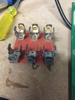
See the two bridge rectifiers just above the transformer with the wires disconnected? I would replace both of those and chop off the old connectors and solder the wires on to the new bridge rectifiers. Remember to put them on the correct way or things will go bang. Then go to the test points on the power supply PCB and check what voltages you have. You probably need a capacitor replacement kit for the power supply PCB.

On and if you didn't disconnect the bridge rectifiers then that is the cause your problem... :cool:
 
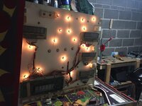
Ok - so I have put back the wires as described - I have a new multi-meter coming Sunday which has clamps as a connection so I can connect as needed and step away then turn the power on read it, then turn it off again. I turned it on out of interest, it didn't go bang, which I thought was good and this happened.

IMG_5297.jpg

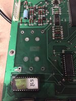
I then looked over the MPU just to review a bit more detail and removed the battery pack which had corroded pretty badly.

IMG_5294.jpg

Cleaned underneath, will solder in a remote battery pack from Maplin when I get one.

IMG_5295.jpg

IMG_5296.jpg

Unfortunately for a family emergency I have to be away Saturday now, but will start metering some stuff up Sunday night potentially if I am back in time.

Appreciate all the help all!
 
No wonder it's not working. From your pictures I can see that you've still got a lot of cleaning and replacing of compenents to do... The chip holder for IC 26 needs replaced and possibly IC 26 depending on the state of the legs. The under side of IC 26 is also affected as I can see in your last photo. The yellow link wire will also need replacing.

You can read up on how to clean and repair battery corrosion here:
http://www.pinwiki.com/wiki/index.php?title=General#Abating_Alkaline_Corrosion
 
^^^^^^ So my eyes weren't deceiving me

Unfortunately not... If I were to take off and clean and re-seat, (along with other affected areas) I am guessing this will make the headache go away...
 
See post 2 here for chip holder replacement procedure...
https://pinside.com/pinball/forum/topic/vids-guide-to-bulletproofing-williams-system-6

Many different methods for cleaning up the battery mess but personally I do this...
After removing the old holder use toilet cleaner, the thick stuff to spot clean the affected areas. Leave for a few minutes then wipe off and rinse with water repeatedly until you are confident the toilet cleaner is totally removed (I strip the boards down and put them through the dishwasher)
Use a wire brush and 600 grit wet/dry paper (or a fibreglass pen) to gently clean up any dulled traces on the board.
Finish your soldering / repair.
Clean up flux and soldering mess with isopropyl.
Cover any bare copper left with clear nail-varnish.

Leave the boards to dry fully before connecting back to power.
 
Moonbus as always really appreciate your input - seems to be a few areas around the leaky battery that will need working on - I will get on with this tomorrow hopefully, if we get to leave early as I am hoping tomorrow, if not at a later date. Toilet cleaner, any brand in particular?
 
Anything acidic. I use the Harpic limescale remover one as it has hydrochloric acid in it. The logic is that the juice from batteries is alkaline and it gets more concentrated as it dries out so by this point you need a strong acid to neutralise it.
The toilet cleaner should be thick enough that you can put it somewhere with a cotton bud and it wont run all over the place and make a mess. Be sure to wash it all off though and don't leave it too long otherwise it can cause the same damage to the board as the battery juice.

Recommend doing this somewhere you can have the windows open.
 
Should I get a certain gauge wire from Maplin that can replace both the yellow jumper wire and conduct the rectifier fuse mod? Also, I guess they don't do the molex male and female connectors, if they do I cannot blooming find them.
 
Ok new meter arrived...


White to White wires - 90VAC - getting 94.0
Blue to Blue wires - 13.5VAC - getting 14.8
Red to red wires - 25.5VAC - getting 28.8 - 28.9
Grey to Grey to Grey wires - This is more tricky but across two of them you should get about 9.3VAC, other combinations will give you less. - 18.5 across one lot - 8.9 across another combo
Yellow to Yellow - 6.3VAC - getting 6.6


This all seems in line to me with what people said of 10% tolerance, so all good I am hoping :)

Also, new meter and didn't blow myself up :)
 
Well done, yep so you know the transformer is all ok, so next check those bridge rectifiers. You know you have a problem(s) with the main board, but may as well check everything else out too
 
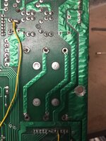
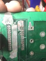
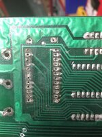
Been cleaning up the MPU - not sure if I am going ok with it or not to be honest. It seems like i need to get back on getting the solder off again and clean off around the traces. Where there isn't a trace it seems there isn't a pad - so getting the solder off here is not working, where the solder had corosion on it, getting it to heat up was a nightmare, think I need a new solder tip too... Am I on the right tracks, or am I making a pigs ear of it and should stop now.

image2(1).jpeg

image1(2).jpeg

Once the whole area is clean I will varnish any bare copper. As well as some of the traces that have any exposed areas.

Whilst IC 26 was by far and away the worst, IC22 will need the same, IC25 will need replacing and resistors C16, C65 and C67.

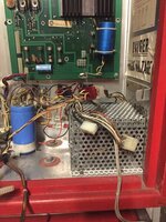
I also did some work around the power supply tonight, adding the 8A SB fuses on the rectifiers (will replace the black wire with blue tomorrow, just didn't have any today and wanted to make sure it worked. I have put the transformer area back together, moved some wires to make it neater and re-cable tied with the mod to make the wires reach.

image1(2) copy.jpeg
 
Back
Top Bottom