What's new
Pinball info

Register a free account today to become a member! Once signed in, you'll be able to participate on this site by adding your own topics and posts, as well as connect with other members through your own private inbox!

In Progress Laser Ball - Williams

James

Site Supporter
Joined
Dec 29, 2017
Messages
5,100
Location
Norwich
Alias
James
Ok - so as a complete newbie, I think I have made either a master stroke of a decision, or a complete £U!K UP - most likely the latter, I have just picked up a Willams - Laser Ball for next to nothing - the cabinet lights up, but does nothing after that (not even the digits light up) - I think I will need to check fuses first and look at reflowing some of the pins, but does anyone know of a place I can get started with some fault finding on this type of unit?

My wife has committed me to friends for dinner tonight, but I will be working it through tomorrow to see what I can see.
 
not familiar with this machine but usually the boards have leds on them - check what they are doing:

machine.cgi

is a link with the manuals.
 
before switch on look inside. check the wiring check the fuses check all connectors. download a schematic circuit diagram and manual from ipdb.org if they have it. check all board connectors. check for any burnt out connectors or components. you could also test out the coils with a multimeter. then if all ok switch on and check the power supply transformer is giving correct voltages. then the power rectifier board then the individual boards. the main cpu board first - i’m sure you’ll find something amiss.


Sent from my iPhone using Tapatalk
 
ps. make sure it’s a 240v machine. is it possible it’s from usa and set to work on 110v ????


Sent from my iPhone using Tapatalk
 
Ok so I have had a quick mosey inside of the cabinet and found a few things out so far - it seems that someone has had a crack at this before and must have given up, not sure when though.

So under the play field I have found a couple of wires put together very shoddily - I am assuming they are in the right place (probably wrong to do so...) but will try and connect them up correctly. Looks like someone has been working some things out on it too...

IMG_5230.jpg IMG_5232.jpg

It seems the upper right flipper has had some work done to it after the build, the guy I got it off says he has had it for 10 years and done nothing with it, although this seems like a fairly new repair, might just be me...

IMG_5232.jpg

In terms of boards, I can see on the CPU there seems to be a connector that doesn't have a chip in it, need to do some research on this, as I say I am a complete newbie at this, but more than willing to learn, so will see what the deal is there.

IMG_5242.jpg

Other boards are here...

IMG_5241.jpg
IMG_5240.jpg


IMG_5239.jpg

Also some quick shots of the play field...

IMG_5238.jpg IMG_5236.jpg

IMG_5237.jpg
 

Attachments

  • IMG_5233.jpg
    IMG_5233.jpg
    78 KB · Views: 11
Here is a link to Part One of Clays epic pin repair guide, if you dig around online you should find parts 2 and 3 somewhere. He took them down but they are archived out there.

http://playpen.icomtek.csir.co.za/~..., Black Knight, Firepower, Gorgar Pinball.htm

Hard to say from the pictures but is there some evidence of battery leak benath the battery holder, around those chips beneath it ?? If so this could cause major headache ...ie ...MPU possibly wont boot
 
Got a few boxs of these left over from my disco shop days.Dont know if there the right ones for you but your welcome to a box for free,i have quite a few boxsSAM_6061.JPG
 
Right then... Well, I wish I just needed some fuses, I am going to need some help with this but I am looking forward to getting into this.

Solenoid Testing

I started off by testing the solenoids, as pictured below, had the multi meter set to 200 OHM and got the following results.

Ammended.jpg

A couple of things to note is as follows:

Left Flipper

The left flipper I am getting 1.9 OHM from, I am guessing that the solenoid here probably needs a rebuild. I imagine this machine will need new springs for both to be honest.

Right Flippers

Both right flippers kicking out 13.2 OHM, is this a little high or to be expected.

MPB

MPB was for a completely missing pop bumper solenoid, was just simply not in place, there is a loose earth and live here, so this must be for the missing solenoid, I have now removed the casing and begun deconstructing the pop bumper, it is missing two parts which I will need to buy, but I will get onto other issues with it shortly.

5-7E

I don't have the most expensive multimeter, but I could not get this to settle down, I notice a loose earth here, which I just cannot place... not sure if this is from this solenoid and would cause the jumpy reading. If not, I have no idea where this is going to go....

IMG_5256.jpg

Pop Bumper

After removing the pop bumper cap, the two wood screws and the solenoid arm underneath, the pop bumper is completely missing - ring and rod nut, pin, spring and bracket and pins for play field side. I don't think I need to remove the bumper now from the playfield as should be able to rebuild from underside, but shouldnt this be able to come out? I cannot for the life of me... "wiggle" it out.IMG_5254.jpg

Earth To Machine

Notice what I assume is the Earth strip going around the machine was completely removed, just reattached this piece.

IMG_5245.jpg

IMG_5247.jpg

Driver Board

This is where I get really worried, the Driver Board has been burnt in many a place. I think I am going to take it into work for a review with our electrical engineer and see if using the schematics he can test the items. It has been scorched pretty bad. Noted that the pins on one of the board have charred and looks to have re-soldered. Interestingly, at 200kOHM across all resistors in areas tested I get consistent readings, not to say they won't be getting changed out.

IMG_5249.jpg IMG_5250.jpg IMG_5251.jpg

IMG_5253.jpg

Thoughts and any suggestions - including cut your losses you are crazy, are welcome.

Thanks for reading.
 
Take what unknown sellers say with a pinch of salt. There are three kinds
  • Idiots who know nothing. They have probably watched the game slowly die over many years and did not have the knowledge or inclination to fix it
  • Knowledgeable, honest folk who may well have maintained the game
  • Liars. The worst of all sellers. They pretend to be idiots but know that they have a basket case on their hands so play dumb
I bought a game from a guy who pretended to have done nothing in many years of ownership. Yet when I got into it the relevant sections of the manual had been annotated and i could see botched attempts to repair the faults the game was sold with

I am inclined to believe they were 1....
Luckily I put very little into it, not that that's the point, I just really need help in getting it sorted, that loose negative is bugging me as I cannot for the life of me work out where it goes.
 
Welcome to the fun.

I'm no expert but I have just been through this ride, this is just my approach.

It looks like the machine has had issues and somewhere along the line the MPU board has been replaced, from what I can find online this should have a system 6 board but your one seems to have an upgraded system 4 board installed.

See section 3.3.6 here on page 13...
http://www.pinballsupernova.com/Williams Repair Guide/Williams System 3 through 7 .pdf

It is not the end of the world, before all hope is lost we must assume the game once worked with this configuration. Question is do you want to play the needle in the haystack game or get someone to fix it for you ?

If you are willing to go on the pinball fix it adventure and find the needle I would do the following, PLEASE BE CAREFUL and know your limits as the last thing any of us want is a human casualty.

The schematics form here...
http://mirror2.ipdb.org/files/1413/Williams_1979_Lazer_Ball_Full_Manual.pdf
...and Clays guide as mentioned above will be invaluable.

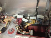
As it sounds like you have some lighting on the playfield it seems power is getting from the wall into the machine ok. The next thing to check is the outputs from the transformer. The transformer should be in the bottom right corner of the head with the boards in, there should also be a ground braid wire that comes up from the lower main cabinet that is terminated somehow in the head box. If the ground is connect proceed to check the voltages on the the pins in the two plugs that come from the transformer and plug into the board above it. Note that these tests will be in AC and that there is usually a high voltage output ranging from 80 to 120vac so again please take caution. I believe a +/- 10% tolerance is allowed so readings may not be exact.

According the the schematic you should have...

White to White wires - 90VAC
Blue to Blue wires - 13.5VAC
Red to red wires - 25.5VAC
Grey to Grey to Grey wires - This is more tricky but across two of them you should get about 9.3VAC, other combinations will give you less.
Yellow to Yellow - 6.3VAC

Next with the power off, plug the transformer plugs back into the power supply board and check the fuses, make sure fast fuses are fast and the slow are slow. also make sure the screws holding the power supply board into the metal brackets are all in place and secure.

Use the continuity test on your multi meter "buzz" to check the power supply board is grounded to the ground braid from the lower cabinet, this is a backup measure. The boards ground trace is where the securing screws go through. It looks from your photos above that you already fixed this braid back to the lower cabinet. It may be worth (with the power off and plug out the wall) buzzing the ground braid repair to the mains ground to make sure its true.

Remove all the perimeter connectors from the power supply board and turn the power on.

Ground your meter to the ground braid from the lower cabinet and test the DC outputs on the power supply board 3J6 connector as per page 8 from the schematics linked above.

Once you have ascertained those are good you can move on to diagnosing the MPU board and see if its playing ball.

Regarding the general state of the boards, its up to you how far you want to dive in but there is an informative thread on pinside that may be of use ( https://pinside.com/pinball/forum/topic/vids-guide-to-bulletproofing-williams-system-6 ).

Happy fixing and be safe.

Guy
 
Last edited:
You can test your coil resistances against this chart
https://www.flippers.com/coil-resistance.html

Note that you will need to remove one of the wires from the coil to accurately test the resistance and repeat the test with the meter probes around the other way just to be sure the diode on the coils is not messing things up. You should get a higher reading over one way then the other.
 
Right, so got this on the bench with one of the lads at work today...

Checking the wiring diagram and the build sheet, worked out that the following resistors are all fried and the whole bank will need to be replaced, seems that something on the play field is causing this, but taking it one step at a time. The other areas though, including the ceramic resistors are all fine.

1st.png

Tomorrow we will review further down the line to see how this has affected other components on the board.

Tonight I am going to check the step down converter, as well as simple continuity checks on the fuses to see which ones have actually gone. I am also going to try and diagnose that loose wire with the wiring diagram and see if that has something to do with the short.
 
Right, so got this on the bench with one of the lads at work today...

Checking the wiring diagram and the build sheet, worked out that the following resistors are all fried and the whole bank will need to be replaced, seems that something on the play field is causing this, but taking it one step at a time. The other areas though, including the ceramic resistors are all fine.

View attachment 57400

Tomorrow we will review further down the line to see how this has affected other components on the board.

Tonight I am going to check the step down converter, as well as simple continuity checks on the fuses to see which ones have actually gone. I am also going to try and diagnose that loose wire with the wiring diagram and see if that has something to do with the short.

All the resistors in the red boxes are zero ohm in value. This may differ from the schematic but is an accepted modification due to switch speed issues and if boards have been used in system 7 games. I'm not sure if it works with system 4 MPU's.
 
@Moonbus - any idea on the pop bumper removal?

Looks like you need a full replacement mechanism. Best place to ask is in the parts wanted section on here, someone is bound to have what you need collecting dust somewhere.
In the meantime just make sure none of the wires under the playfield are able to touch anything else or each other unless they are wires of the same colour that loop on to other mechanisms.

I can get the mechanism from a few online sites, just getting the blighter out...

All the resistors in the red boxes are zero ohm in value. This may differ from the schematic but is an accepted modification due to switch speed issues and if boards have been used in system 7 games. I'm not sure if it works with system 4 MPU's.

So would replacing to schematic standard cause an issue? I think we are getting random varying values out currently.
 
If you are trying to remove the pop plastic have you removed the staples from the lamp socket wires on the underside of the playfield?

If the plastic is not broken leave it be or you may have to add the lamp socket to your shopping list.
 
Hello, James,

If I may offer some advice, it's important that the loose earth braid at the rear of the cabinet is fed up into the backbox, and attached to a small earthing stud on the base panel of the b/box with a wing nut, to earth the metal panels (and the circuit boards) in the b/box

The vacant IC socket isn't necessarily anything to worry about, as only one pre 'Level 7' game (FirePower) used all six sockets for program chips. This board seems to have 'Green label Flipper Rom(s) 1 & 2, and three 'personality' PRoms, it may be worthwhile to check if possible that they're placed in the correct sockets

The label on that driver board shows that it was originally installed in a later level 7 game, Black Knight, which required the use of zero-Ohm jumpers in place of resistors. But this alteration was for the switch matrix inputs, not the solenoid outputs

Re the seemingly redundant Grey-violet wire, as I suspected, Laser Ball used two separate solenoids on the 4-target bank, one for targets B and A, the other for the two L's. It looks like one solenoid, sleeve, reset plate, etc, is missing
 
Last edited:
Something that can be addressed whilst you have the boards out of the machine is the removal of the battery holder. Whilst some will say just stick lithium batteries in it that will not tell you what is underneath it and if there is indeed any battery damage.

http://www.pinwiki.com/wiki/index.php?title=File:WMS_sys4_MPU_board.JPG

If however you decide to send the board out here is an idea of what it will go through...Also gives you an idea of what to look for regarding the MPU lights.
 
I had a gorgar playfield which I have striped ages ago PM me a pic of the parts you need and I will see what I can find :thumbs:
 
Hello, Adajam,

If I may offer some advice,

Yes please, I really need it and it is all much appreciated

it's important that the loose earth braid at the rear of the cabinet is fed up into the backbox, and attached

Ahh yes, I attached it back to the cabinet before - silly, but I have now moved it up to the backbox as recommended.

Hello, Adajam,

The vacant IC socket isn't necessarily anything to worry about, as only one pre 'Level 7' game (FirePower) used all six sockets for program chips. This board seems to have 'Green label Flipper Rom(s) 1 & 2, and three 'personality' PRoms, it may be worthwhile to check if possible that they're placed in the correct sockets

As this is a system 4 game, will it work with the required system 6 game? I am guessing that, as @Moonbus stated, we can assume it was at some point working, but with your knowledge, does this look plausible?

Hello, Adajam,

The label on that driver board shows that it was originally installed in a later level 7 game, Black Knight, which required the use of zero-Ohm jumpers in place of resistors. But this alteration was for the switch matrix inputs, not the solenoid outputs

Given this, would it be worthwhile to replace this with the required resistors for this game, as have seen that this is not in line with spec for this game.

Re the seemingly redundant Grey-violet wire, as I suspected, Laser Ball used two separate solenoids on the 4-target bank, one for targets B and A, the other for the two L's. It looks like one solenoid, sleeve, reset plate, etc, is missing

Yes, absolutely, in fact, I have done a bit of work around this drop target assembly tonight, the Grey and Blue wire should be attached to another drop target solenoid as discussed, according to the schematic, the "BA" drop targets, which is 100% correct, what the previous person has done is disconnected, then bridged the two red power wires. To keep the game.... "running" they have extended the target lift with a piece of...

IMG_5275.jpg

IMG_5274.jpg

I have removed this and will add the the required parts to my shopping list.

Out of interest if anyone knows, would these two solenoids being missing cause the game not to boot? Seems strange, but... it wasn't. The solenoid fuse was indeed blown too.

For the left pop bumper solenoid, this is the missing blue brown wire, and the return and entry red power line.

As for working these bits out for myself tonight I removed and gave a little clean to the top plastics which were catching as I lifted and dropped the play field.

IMG_5270.jpg

Half way through the clean, you can see the difference....

IMG_5271.jpg

Well... I could.
 

Attachments

  • IMG_5266.jpg
    IMG_5266.jpg
    135.2 KB · Views: 13
  • IMG_5272.jpg
    IMG_5272.jpg
    61.4 KB · Views: 11
There were some games (Gorgar being another instance) where the instructions regarding replacement boards said that though an L6 or later board would be preferable, an L4 with sufficient sockets was acceptable but the 'Memory Protect' wouldn't be available. That meant that the white microswitch operated by the coin door wouldn't prevent the factory settings being loaded up if there was a loss of battery back-up power to the Cmos Ram. Important to an operator, but not so much in domestic use. Referring to the manual for an L4 game shows that the vacant socket should be the furthest to the right, with IC's 17, 20, 21 & 22 moving from right to left, and 26 in the upper socket. If those labels are to be trusted, the program chips are positioned correctly

The alteration to the driver board was justified by the later multi-ball games having to keep track of 2 or more balls in the machine, apart from being in play simultaneously. I'm not sure if it's essential to have the resistors on earlier games, but it couldn't hurt to change them over

A lack of solenoid power shouldn't stop the Cpu from booting up
 
not an expert in these older machines but have you tried disconnecting things to see if the CPU will boot?


HA! WOW - yea it really could....

not an expert in these older machines but have you tried disconnecting things to see if the CPU will boot?

Going to see if the electrical engineer at work will let me borrow a bench power supply to boot it, or take it in to him Thursday, we are working through the driver board first off,so one thing at ta time I guess. Just getting into the swing of it and I want this project to be methodical and enjoyable, which right now I am loving... already wondering... what next!
 
When I had my Gorgar the first time I powered it up ,I had to have the coin door open to get it in attract mode ,then after that it was fine ,was told later it was because we took the head off to transport it !
 
When I had my Gorgar the first time I powered it up ,I had to have the coin door open to get it in attract mode ,then after that it was fine ,was told later it was because we took the head off to transport it !

I am going to do some more due diligence with the driver board, then get my work guy to check the power board over, get the solenoids in and some checking of the playfield wiring, then start to look over the boards power supply once back in too. Then I will go for this with the coin door, I am hoping in a week or so to be at this point... lol

A bit worried that the display wasn't booting when I looked over it, think that is a bad sign.
 
I would not worry to much at the moment.

If the transformer is good then the power supply board can always be fixed.

If the power supply board is working then the MPU can nearly always be fixed.

If the Power Supply board and the MPU work the driver board can nearly always be fixed.

With the above all working the displays can be fixed or replaced.

Without fire there is always light at the end of the tunnel.
 
Back
Top Bottom