What's new
Pinball info

Register a free account today to become a member! Once signed in, you'll be able to participate on this site by adding your own topics and posts, as well as connect with other members through your own private inbox!

In Progress Laser Ball - Williams

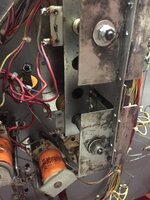
If it helps, my procedure with flipper coils is to regard them as similar to normal solenoids.
  • The banded end of the diode shows which terminal to apply the supply wiring (and no other, with Williams games like this)
  • The plain end of the diode shows where to connect the return/ground wire, it's no matter whether this leads to a button switch and relay contacts or a drive transistor/relay driver
  • The coils' own End of Stroke switch connects across the centre and plain/return terminals, shorting out the secondary winding (on serial-wound coils like these)
  • An additional Normally-Open switch for an extra flipper connects to the tail end of each coil (plain ends of the diodes) to complete the return for the 2nd coil when it closes
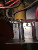
In the picture of the lower flipper, it seems that the return wire (Blue-grey?) is attached to the centre terminal, rather than the tail (plain/anode end of the diode)

A check that can be made for operation of an additional flipper switched this way is to manually raise the lower flipper paddle, operating the switch, and then press the flipper button. Provided that the relay is On, the upper flipper should operate normally as the button is pressed

The solenoids that have locked On are the six designated as 'Special' solenoids. They're isolated and enabled as a group, by the same logic circuits that control the flipper relay.
 
Last edited:
Hi @Jay Walker - absolutely this does help, I am 100% sure when wiring in the new solenoids that they had the red wire (i.e. supply) was to the banded end of the diode.

I will recheck the solenoid wiring on the flippers, as I know I have messed up by putting the extra normally open on the middle of the upper flipper :oops:

I agree that the six wired ones are all special solenoids, so something is amiss there, but also, it seems that the ball release locks on too...

Screen Shot 2018-03-03 at 13.11.03.png

This wouldn't form part of that special solenoid group would it... I will check that there isn't a short in the wiring there touching onto something it shouldn't.

Screen Shot 2018-03-03 at 13.14.47.png

I am going into the garage now to put the heating on, so in an hour I can get out there and have a tidy up and move some stuff around etc. to get it how I want it to focus more on this, especially as I now only have 1,000 words left of my MBA and I need something to fill my time :clap::clap::clap:
 
In fact, the left side eject pocket isn't a Special solenoid, as I originally thought, the Ball Release and the Left pocket are 'normal' solenoids 1 and 2. A first step with locked-on coils is to detach the return connector(s) from the driver board, 2P11 and 12 in this case. If the coils still lock on, they're grounding through the wiring somehow. If they don't lock on with the connectors removed, the problem is on the circuit board.

Looking closely at the drop target bank, does the replacement coil have a diode on?
 
Last edited:
Hey @Jay Walker - thanks for the input.

Locking on with plugs removed, this is cause for hope I am hoping, as this means the board is good right. So need to find that short. Is there a method of finding a short? Need to reread posts probably.

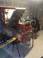
Set my garage up today to allow me to flip over the playfield onto some jockey supports to get to the wiring. I will get this done. Feeling more positive today. Thanks for the stream @Neil McRae whilst I wasn’t getting this done.

61720D7A-D9E3-4F32-9142-F1A5516C56CF.jpeg

As for the replacements coil, this has a diode on other side not shown in the picture, was wondering that myself at first.
 
Last edited:
As for the replacements coil, this has a diode on other side not shown in the picture, was wondering that myself at first.

Doesn't matter which side the diode is on. It does matter that you check the coil resistance first before fitting (typically 4 ohms) and that you connect the wires to it the correct way round. I can see that they're not by comparison to the other coils in your photo which is why I stated that you've got it connected wrong... :rolleyes:
 
img_5668-jpg.60169


Thanks for the input @Moonraker - I am assuming that you are referring to this set of drop targets. Where left to right we have Ground - Live ---- Live - Ground, I copied the wiring of the reused coil on the left as it were in Gorgar, as this is a similar drop target reset, i.e. it should pull the pin upwards, so it does seem strange to me the polarity as it were be different, is there a way to determine which of these two is right to complete the required reset function, as I am not sure now which way is right.
 
Furthest coil is upside down by comparison to the other two. Black wire on the left lug, red wire on the right lug. Middle coil black wire on the left lug, red wire on the right lug. Nearest (the replacement) coil, left lug has red wire, right lug has black wire which is the opposite of the other two coils in that picture... hence incorrectly wired. Can't tell what direction the diodes are installed on any of the coils but chances are that it might be installed the wrong way round...

Have you checked the coil resistance? If it's a knackered coil with a short on it, then it would be moot point which way round it's fitted..!

Oh and just seen that you also need to trim the coil sleeve on the replacement coil as it's too long so the drop targets might not reset properly... Compare it to the middle coil.
 
I think my bad picture taking may not be helping, it’s a drop Bank with two solenoids - the left one being the Gorgar replacement, right being original and wired in situ although the previous owner had left the two red wires attached together but not soldered to anything.

2BD6304A-1A28-4CE1-AB33-E4BF67A47440.jpeg

And you look at this the clear sleeve from
Gorgar is reading 2.3 on DMM and the orange sleeved, 3.9 on DMM. Gorgar one is red attached to how it was on Gorgar, and below picture hopefully shows diode right way round although does look a bit ropey...

3069F00A-60D8-430D-9BEA-651DCCDA940E.jpeg
 
My mistake about which one was the replacement. So the one wired in situ although the previous owner is wired incorrectly and need the wires swapping over.
 
Diode banding is currently on left lug, so will need switching to right lug, along with red wire I am gathering.
 
Didn't manage to get in there today to have a go at this, but would that one wrong wired solenoid cause locking? It wasn't locking previously with this wired this way...
 
While the return connectors are detached, each coil return should be isolated, so I think a continuity check to ground (and the other returns) should show open circuit.

I'd be wary of that replacement coil. Besides the diode, which may have been added at some stage, the sleeve isn't right for a drop target reset. And there's no sign of what it actually is. The r/h coil is correct.
 
Thanks @Jay Walker - for the money, I will buy new from @pinballmania when the rest of my order goes in, I will try to desolder and see what happens, as issues only started after this and another similar pop bumper coil were added, however prior to this, these solenoids didn't work. If this is a grounding issue, as per taking the wires off of the driver board, what would the approach to finding the short be? Taking off every coil, snipping diode and checking?
 
With the circuit board connectors still detached, use a meter to check ohms or continuity between an affected return and ground, which I expect will show a low resistance/good continuity. Check along the route of the return wire for any sign of a short circuit, removing anything found before re-applying power to the circuit (disconnect the meter before doing so). With the return connectors detached, current should have nowhere to go, leaving the coil(s) dormant.
 
So by this you mean the non power side of the coil (i.e. the coloured side) and the grounding braid around the cabinet, or the corresponding molex connector that should connect to the driver board.
 
So for all who took part in the idiot of the year awards, I want to say thank you for trying, but I have absolutely destroyed you here this year, turns out, connecting the wiring for the lamps to the solenoid ones, will probably cause locking on :eek:

Noticed once the 2.5A SB on the board was out (going back to my initial checks, this was out when I bought it) so I should have known something was up. Well, another lesson down in the books,

Keep
It
Simple
Stupid

:oops::oops::oops:

Right flipper is still just moving upward and top right flipper non responsive, I imagine the right coil, a new one is needed I am getting ohms across the lugs however, top flipper still unresponsive.

So, for the solenoid just blowing, assuming that this was happening prior to owning as the fuse was out when I got it, would it be a safe assumption there is a dodgy coil somewhere in the system? De solder all, replace into system one by one and go from there? The soldering on some of the coils is... messy at best anyway.
 
Took off all plugs, turned on with new fuse, didn't blow.

Reconnected ground, 2J12 and 2J13 and fuse still intact.

Something on 2J13 which has all drop targets on it, must be causing short and blowing it Will be checking which one Wednesday now.
 
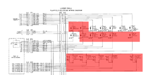
acording to the IPDB drawing I have...

2J13 should be left, center and right Jet Bumpers and the two kickers
2J11 has the drops on it.
3J3 is the live - Pin 1 to 2J11 and 2J12, Pin 2 goes to 2J13
 
So tested all the solenoids to find out which one is causing the issue and only one has a short, firing on startup... can anyone guess which one.... yep... it's this beauty...

3069f00a-60d8-430d-9bea-651dccda940e-jpeg.60275


Not sure what to do really, just shotgun it and order new coil, TIP120 and 2N4401 and be done with it. Anyone know if you can buy these effectively in 5's or if it has to be a bulk purchase?
 
If this game has any un-used solenoid drives, these could be transferred to the affected circuit. Adding up quickly, there are 10 solenoids, 5 used to select sounds, and 5 Spec. solenoids, so there should be a couple left over.
 
If it fires on startup and does not lock on its working as it's resetting the drop target. If it fires and locks on then the transistor on the driver board is bad.
If the other drop target is not resetting then thats where the problem is.

First thing I would do is put new diodes on those coils and see if the issue is still there, then swap the coil grey wires over, the grey/blue and the grey/purple. This will give you 100% certainty of where the error lies.

When you are testing the coils be sure to remove the single wire from them, in this case the grey ones and test them with the DMM in both directions. You should get almost zero ohms in one direction and a suitable ohms in the other direction as per this chart https://www.flippers.com/coil-resistance.html.

If you need to replace the transistors on the board I find RS is the most efficient way, make sure you only order in 5's or 10 and not the 50's, 100's or 1000's. Or as suggested find one that is not used on the board, desolder it and swap it in for the suspected dud.
 
Yes, the coil will be alright. The original was probably removed due to it having burnt out. According to the booklet, the B-A reset is assigned as Solenoid 6, driven by transistor Q 25 (and its pre-driver)

I'd forgotten that Laser Ball has a flashbulb circuit, so in fact there's only one unused drive circuit, 'Special 5', # 21, Q 10. Though unless you want to actually use the coin acceptors, the drive for the lock-out solenoid on the door could be sacrificed (# 16, Q 45)
 
Last edited:
Thanks @Jay Walker

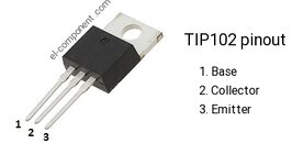
I have ordered some TIP102's, 2N4401's and some 1N4004 diodes, I plan to take the coils out, cut the diode off of it, re-solder new diode, take off board, replace Q25 (TIP102) and the associated 2N4401 - just to confirm, I have seen elsewhere that the legs can need swapping for newer transistors, is that the case with the TIP102, or is a straight swap?
 
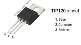
The 'transistor' package used for these solenoid drives is a TIP 120, or the uprated 121/122's. I think a 102 may be the wrong polarity.
 
These pics are probably irrelevant but they're both NPN type that counts.

www.el_component.com_images_bipolar_transistor_tip102_pinout.jpg
www.el_component.com_images_bipolar_transistor_tip120_pinout.jpg
 
Last edited:

So i changed over the foul and disconnected the upper flipper, checked the wiring (document said blue and violet was return left flipper button on checking in cabinet - it is actually the right button so that was right) - this has been in another machine though, where it worked fine on the right flipper and the upper right flipper. So
This must be a wiring issue, but what could cause this?
 
Back
Top Bottom