What's new
Pinball info

Register a free account today to become a member! Once signed in, you'll be able to participate on this site by adding your own topics and posts, as well as connect with other members through your own private inbox!

BOP New issues - Head motor/switch error

cr5000462

Registered
Joined
Apr 25, 2020
Messages
599
Location
Wrexham
Alias
CR
Hi All,

Another electrical issue here im struggling with,

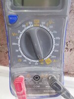
BOP has DMD power only, I have checked all the fuses and they seem fine,
There is zero power to the playfield or backbox display lights.

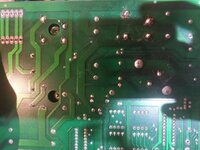
The board LEDs are as follows :
LED 1 - on
LED 2- off (apparently should be on)
LED 3 - on (apparently should be off)
LED 4 - on
LED 5 OFF (its the +20V, apparently should be ON)
LED 6 - on
LED 7 - on

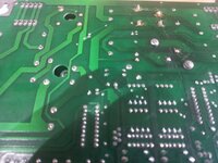
D19 - on turn on it lights up for seconds then goes off, which is working fine.
D20 - Flashes constantly, again working fine
D21 - Constantly on, again fine.

Ive been stuck on this for a few days now, Any ideas?

https://www.pinball.co.uk/pinball-problems/wpc-leds-explained/
 
Sounds like your power driver board is ‘blanked’. That’s the state it’s in during power up and when blanking is removed allows the the driver board to do its thing.

Check the short grey data cable between cpu and driver.

If you’ve removed it for any reason then check that you haven’t missed a row of pins when you put it back on. Otherwise remove the cable, turn it upside down and put it back on again be careful to not miss a row.

Led 5 is for flash lamps, it won’t stop the machine booting. LED 2 doesn’t really mean much IMO
 
Morning,

So Ive just put a new data cable between cpu and driver board, LED2 is now on, as well as LED3.

But LED 5 is still off and there is still no power to the PF or lights :hmm:
 
As andy mentions above you've most likely got no data going to you driver board if your playfield is totally dead but your cpu is running (as noted by your cpu board leds)

However, its pics time now i think, take some pics of the cable you just installed so we can see what its like and also the full backbox of boards.

Also, its best to measure the voltages on the driver board at each test point, not just assume voltages are good if the led is on. However its unlikely everything would be dead if some of the leds are on.

The lack of 20v normally means the fuse is blown at F111 and possibly the associated rectifier is shorted/dead. You'll get no flashers when this isnt working.
 
Reseat all cable connections on the driver board. Could also be dry joint on the pins onto the pcb, try reseating all connections first.
 
I've had a clean of the wiring and pins,used a new ribbon and we have light!

Playfield looks for the pinball aswell,

No flashers though the 20v is still out,
Checked the fuses, :popcorn:
 
Last edited:
With all cables out except j101 and 102, the ribbons.
20v is still out.

So it's a board issue?
 
Think o might have found the issue.
Board removed
Corrosion on the back of br4, the resistor thing and br2
 

Attachments

  • IMG_20200601_153831.jpg
    IMG_20200601_153831.jpg
    131.5 KB · Views: 30
Think o might have found the issue.
Board removed
Corrosion on the back of br4, the resistor thing and br2

thats where someone has replaced the rectifier at some point and not cleaned the flux off the solder after.

did you check the f111 fuse?

you can use diode test to check the rectifier for shorts to
Or send the board to someone to test seperately and repair like me :)
 
Yes f111 fuse is fine,
I'm really trying to learn how to do a few things myself, but will end up sending it off, I can solder etc, it's the fault finding I haven't got a clue where to start
 
Yes f111 fuse is fine,
I'm really trying to learn how to do a few things myself, but will end up sending it off, I can solder etc, it's the fault finding I haven't got a clue where to start

If you want to try and sort it yourself thats cool, i and others will help you diagnose, or if you want it tested/fixed quickly then send it to me and ill sort it out

To test the rectifier you need a multimeter on diode test. Then you check each diode in both directions using the leads. The diodes are originated around the edges of the square rectifier so each 2 pins on 1 side is a diode (or thats how you think of it anyway)

If the fuse isn't blown then its leading more to a bad previous repair (not uncommon ) and a bad trace somewhere.
 
To test the rectifier you need a multimeter on diode test. Then you check each diode in both directions using the leads. The diodes are originated around the edges of the square rectifier so each 2 pins on 1 side is a diode (or thats how you think of it anyway)

Am I right in thinking that you should get a beep one direction & not the other if the diodes are OK?
 
How did you check the fuse? You can not rely on looking at it. It needs to be tested with a meter. And if tests with a meter it needs to be removed from the circuit as you’ll get false results. 10-1 the fuse falls apart when you pull it out.
 
I have a multimeter, ohms, out the board one either side of the fuse.

Readings between .5 and .7
 
So, I've put my meter to diode test
Flipped the board over so I can see the back,
Put the red on the plus and black on neutral.

The br to the right of the faulty corroded bit gives me readings. 472 and 466 (br3)

When I move to the corroded br4 there is nothing at the top. But at the bottom I get 422.

The other bridge br2 at the top left gives me 491 and 468

Which go me shows br4 is duff?
 

Attachments

  • IMG_20200601_170122.jpg
    IMG_20200601_170122.jpg
    95.9 KB · Views: 12
  • IMG_20200601_170139.jpg
    IMG_20200601_170139.jpg
    93.6 KB · Views: 12
Hey mate, how many projects you got on the go at the moment :)
Just down to 3 now, wh20, taxi and bop, out of my stash Congo,roadshow and wh20 are my favourites, rest I'll swap for some other game like junk yard or similar
The wh20 works just needs a bit of tweeking
 
Thanks Vimto, I have been doing that, I think its BR4, well followed the youtube video that shows how to test bridges and it appears BR4 is goosed,
would BR4 stop the head from working... I feel that may be an entirely new subject once I have 20V back :hmm:
 
Ok Check for tracking and dodge repairs issues as others here have mentioned.

Probably bad tracking . Rectifiers do go bad so dont discount it.

Look online and view how to test a Bridge using a meter
 
Ok Check for tracking and dodge repairs issues as others here have mentioned.

Probably bad tracking . Rectifiers do go bad so dont discount it.

Look online and view how to test a Bridge using a meter

It is the bridge, I watched the youtube video on how to test it with my multimeter, its dead at BR4
 
Update, br4 has been changed and I the 20v led is on again :)

Sadly, still not head movement,no head lights, and only a few flashers in the board:hmm:
 
Hi Folks,

Really stuck here, wondering if anyone can offer a pointer or two.

I have power to the playfield now, seems that the 5,12 and 20v all work (I changed br4 to get 20v working)
I have full GI except for the lower playfield - slingshots
All flashers etc work, all playfield targets, pop bumpers etc work.

I keep getting head motor and/or/switch error when I test, The head does not spin, but the ball pops out of her mouth, left and right eye switches work and verify as working in the test menu.

the head will not move manually in test, and will not calibrate.

I removed the motor and tested that on a separate supply, it spins and works.

I have fitted a transistor and heatsink to the motor regulator board as It was originally missing, I have power to the motor regulator board, and it seems to be leaving the board as well, but slightly lower voltage.

there is voltage to switch 67, the switch is normally off when I close it there is a voltage between the two.

It lets me start and play a game, but there is zero life in the head spinning.

Really stuck here on what's going on.. or not going on!


oh, and finally, but probably not related, the sound doesnt seem to be coming from the speakers, the volume has to be cranked right up to hear the slightest of audio noise, and it seems like the sound is actually coming from the board not the speakers?!?!?! is that even possible

Bribery here, but whoever cracks it gets a beer, and a nice £50 donation to the forum for the consistent help that this forum brings (bribery seems to be my last resort :rofl: )
 
Let me dig out the schematics and i'll get back to you on the motor. There are a few things you can test to isolate where the issue is.

As for the sound board, the best thing for that is to send to me for investigation/reapir and testing in another game.
 
Ok, so the design is pretty simple You have a regulator board that takes 20v in and outputs 12v and then you have a relay that is controlled by the driver board (2 drives) to switch the 12v to the motor.

Start with the basic and manually ground the relay at pin 2 to see if it turns the relay on. It the relay clicks then you can ground the pins at 5&6 to see if the head motor then turns on.

Next measure the output of the regulator board and make sure its 12v. If it isnt then the issue on that is likely to be the zener diode (D2) which is a very basic voltage regulator.

Also measure the 12v input to the relay at pin1. (This is may be a 12v feed separately from the above 12v creation). and the 12v at relay pins 4 &7

See the schematic below

bride-of-pinbot-head-motor-schematic.png
 
Last edited:
the relay only changes the direction of rotation
grounding the blue/yellow should cause rotation, solenoid transistor on driver board maybe faulty
 
Thanks for the info, I will have a play this afternoon and follow your advice then report back.

My plan for the sound board is to send it off to you along with the taxi board, just want to get the head going on BOP, slowly working down a loooooong list between a few games, but bop is the only one giving me the headache
 
Back
Top Bottom