Pinball info
You are using an out of date browser. It may not display this or other websites correctly.
You should upgrade or use an alternative browser.
You should upgrade or use an alternative browser.
BOP New issues - Head motor/switch error
- Thread starter cr5000462
- Start date
Then there is no 20vdc.
You need to trace that back. I dont have any drawings . Probably a fuse or bad wiring?
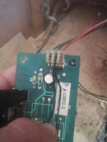
Is the black wire looping through? as nothing is shown connected on pin 3 on the drawings I do have for the reg circuit
You need to trace that back. I dont have any drawings . Probably a fuse or bad wiring?
Is the black wire looping through? as nothing is shown connected on pin 3 on the drawings I do have for the reg circuit
Seeing as your testing whislt powered you could be blowing the fuse.
Be careful as you can damage other IC's.
Change the fuse without the motor reg connected and test the 20vdc.
If ok then connect and see if it pops.
Be careful as you can damage other IC's.
Change the fuse without the motor reg connected and test the 20vdc.
If ok then connect and see if it pops.
Last edited:
- Joined
- Jul 21, 2011
- Messages
- 2,527
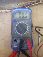
You have your test leads in the wrong place in the meter. The black lead should be on the centre hole marked com, and the red where it is.
The left hole is a second option for the red lead if you are measuring current through the device.
The left hole is a second option for the red lead if you are measuring current through the device.
- Joined
- Jul 21, 2011
- Messages
- 2,527
Sorry. To be clear. Your red lead should be on the right hand side. Black in the middle.
- Joined
- Jul 21, 2011
- Messages
- 2,527
I didn’t clock that you had them reversed initially. If you have red in left then you’re putting a short across the circuit v
- Joined
- Jul 21, 2011
- Messages
- 2,527
Yes. That’s correct.

OK then the relay is working .
You need to test that you have 12vdc at J2 pin 4/7 on the relay board.
Use J2 pin 2 on the regulator board as your gnd reference. So place your black probe from your meter on here.
Red probe on relay J2 pin 4 or 7
You need to test that you have 12vdc at J2 pin 4/7 on the relay board.
Use J2 pin 2 on the regulator board as your gnd reference. So place your black probe from your meter on here.
Red probe on relay J2 pin 4 or 7
Thanks,
I use Gnd on j2-2 as suggest
And place red on pin 7 of the relay board and get 0.
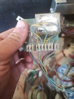
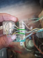
When I look at the relay board.
I am working right to left.
So furthest right pin 1, furthest left is pin 7.
Then the two separate pins start again as pin1 and pin2 ? Again pin one being on the right
I use Gnd on j2-2 as suggest
And place red on pin 7 of the relay board and get 0.
When I look at the relay board.
I am working right to left.
So furthest right pin 1, furthest left is pin 7.
Then the two separate pins start again as pin1 and pin2 ? Again pin one being on the right
Attachments
Reread my previous message as the connections are for the two boards.
Use J2 pin 2 on the regulator board as your gnd reference. So place your black probe from your meter on here.
Red probe on relay board J2 pin 4 or 7
Use J2 pin 2 on the regulator board as your gnd reference. So place your black probe from your meter on here.
Red probe on relay board J2 pin 4 or 7
Must be an error on the drawing as Gnd should be there.
So 12dc is OK.
I dont have the complete drawings but guess that the driver board pulls down relay J2 pins 5&6 down to gnd to turn on motor.
Can someone check to see if it's oK to pull them hard down to gnd please.
So 12dc is OK.
I dont have the complete drawings but guess that the driver board pulls down relay J2 pins 5&6 down to gnd to turn on motor.
Can someone check to see if it's oK to pull them hard down to gnd please.
I think when I removed 5&6 and put them to braided wire last time that is what blew the fuse, as last night I had 20v
To test it out its best to remove that connection at the drive board. Not sure what that is as no drawings
That way we can pull the relay board J2 pins 5&6 to gnd and the motor should spin
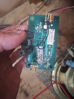
I chased the blue yellow back to the board.
It goes to j122-4
I tugged it and it came off in a huge strand! It must have been broke off already!
I chased it back to the join,
Put it to gnd (braided wire, in the backbox)
Still nothing.
It's still connected on the relay board when I'm doing this, should it be?
I've tested this out of all settings tests and again with it on manual head test motor on
No I think you just stripped the outer off.
Check the connector going to the motor when that wire is connected to gnd you should have 12vdc on the output to the motor.
Pins 1&2.
and test the motor on 12v.
Also check that there are no dry joint on the relay board as @Spandangler mentioned.
Also check continuity of all wiring thats involved.
I dont think I can suggest anything else.
Maybe @pinballmania has any idea's