Pinball info
You are using an out of date browser. It may not display this or other websites correctly.
You should upgrade or use an alternative browser.
You should upgrade or use an alternative browser.
BOP New issues - Head motor/switch error
- Thread starter cr5000462
- Start date
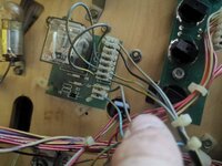
Start with the basic and manually ground the relay at pin 2 to see if it turns the relay on. It the relay clicks then you can ground the pins at 5&6 to see if the head motor then turns on.
Okay, so I've got the tester out, put red on pin 2 and black to ground, nothing clicks on the relay
There was an issue early on when the flashers came on the relay was clicking like crazy with every flash, I compared boards and wiring to a friend on WhatsApp and I had an extra wire in j125 pin 1
That wire in his machine was going to j122 pin 3, when I did the same the relay stopped clicking when the flashers turned on and off
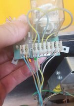
Pictured attached below")
And the other side?
There was an issue early on when the flashers came on the relay was clicking like crazy with every flash, I compared boards and wiring to a friend on WhatsApp and I had an extra wire in j125 pin 1
That wire in his machine was going to j122 pin 3, when I did the same the relay stopped clicking when the flashers turned on and off
Did you find a wire to go to J125 pin 1 ? If so what was it?
Oh and the relay only controls the direction of head turning.
I would see if you have voltage across J2 pins 4 and 5, also 6 and 7 when the head drive is powered from motor regulator assembly - you did say that " I have power to the motor regulator board, and it seems to be leaving the board as well, but slightly lower voltage.".
I would see if you have voltage across J2 pins 4 and 5, also 6 and 7 when the head drive is powered from motor regulator assembly - you did say that " I have power to the motor regulator board, and it seems to be leaving the board as well, but slightly lower voltage.".

Hi Folks,
This is where I currently am with the help of a good forum friend on whatsapp, Not sure of your forum name but thanks for the continued help for several weeks on this carl!
When I now go into test mode and manually test the motor, I Can hear the relay clicking in and out when it goes to on or off, but the motor does still not spin.
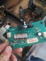
focusing on the motorhead board now :
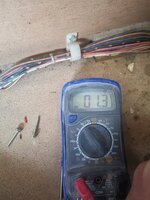
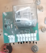
When I test for 20v at the motorhead board, by putting red probe on J1 and black on J1-2 I get -23.5 (yes minus)
When I put red probe on J2 pin 1 and black on a braided wire I get 12.9V (NOT A MINUS)
Testing across pin 2 and pin3 on J2 I get -12.9 (MINUS AGAIN)
Testing across pin 1 on J2 and pin 2 on J1 I get 10.3 (NO MINUS)
Testing pin 1 on J2 and 2 on J1 I get -12.9 (again a minus)
So it seems that 20V and I am getting 12V out which appears to be fine, not sure when is im getting a minus and not sure when the motor isn't spinning?
Do we think that the regulator board is fine, and I should now move onto testing the relay board?
This is where I currently am with the help of a good forum friend on whatsapp, Not sure of your forum name but thanks for the continued help for several weeks on this carl!
When I now go into test mode and manually test the motor, I Can hear the relay clicking in and out when it goes to on or off, but the motor does still not spin.
focusing on the motorhead board now :
When I test for 20v at the motorhead board, by putting red probe on J1 and black on J1-2 I get -23.5 (yes minus)
When I put red probe on J2 pin 1 and black on a braided wire I get 12.9V (NOT A MINUS)
Testing across pin 2 and pin3 on J2 I get -12.9 (MINUS AGAIN)
Testing across pin 1 on J2 and pin 2 on J1 I get 10.3 (NO MINUS)
Testing pin 1 on J2 and 2 on J1 I get -12.9 (again a minus)
So it seems that 20V and I am getting 12V out which appears to be fine, not sure when is im getting a minus and not sure when the motor isn't spinning?
Do we think that the regulator board is fine, and I should now move onto testing the relay board?
Last edited:
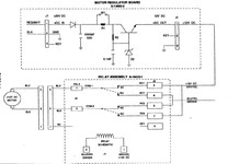
Look at pg 3-3 of the manual. That has the full schematic of the motor reg and relay circuit.
Pretty straight forward.
The motor reg just supplies 12v to the relay board. j2
1.The relay board uses that 12vdc gn/yel .
2.The relay board also has a switched pulldown from driver board. blu/yellow
1 and 2 are swapped by the driver board relay coil control on j1
Its not going to move unless 12vdc is applied to j2/4 0r j2/7
its not going to move unless j2/6 j2/5 is not pulled down
its not going to move if 12vdc is not applied to j1/2 and drive is not pulling down j1/1
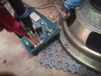
To get the motor moving disconnect j2/5 j2/6 and connect to gnd
To change direction disconnect j1/2 and connect to gnd
To simplfy all that is being done is 12vdc is being applied and driver board is pulling down pins to gnd.
Pretty straight forward.
The motor reg just supplies 12v to the relay board. j2
1.The relay board uses that 12vdc gn/yel .
2.The relay board also has a switched pulldown from driver board. blu/yellow
1 and 2 are swapped by the driver board relay coil control on j1
Its not going to move unless 12vdc is applied to j2/4 0r j2/7
its not going to move unless j2/6 j2/5 is not pulled down
its not going to move if 12vdc is not applied to j1/2 and drive is not pulling down j1/1
To get the motor moving disconnect j2/5 j2/6 and connect to gnd
To change direction disconnect j1/2 and connect to gnd
To simplfy all that is being done is 12vdc is being applied and driver board is pulling down pins to gnd.
Look at pg 3-3 of the manual. That has the full schematic of the motor reg and relay circuit.
Pretty straight forward.
The motor reg just supplies 12v to the relay board. j2
1.The relay board uses that 12vdc gn/yel .
2.The relay board also has a switched pulldown from driver board. blu/yellow
1 and 2 are swapped by the driver board relay coil control on j1
Its not going to move unless 12vdc is applied to j2/4 0r j2/7
its not going to move unless j2/6 j2/5 is not pulled down
its not going to move if 12vdc is not applied to j1/2 and drive is not pulling down j1/1
To get the motor moving disconnect j2/5 j2/6 and connect to gnd
To change direction disconnect j1/2 and connect to gnd
To simplfy all that is being done is 12vdc is being applied and driver board is pulling down pins to gnd.
Hence my post a month ago on 10th June:
I would see if you have voltage across J2 pins 4 and 5, also 6 and 7 when the head drive is powered from motor regulator assembly
GND = earth = 0v
the schematic is a theoretical circuit diagram , to make the schematic easy to read they lay it out logically and not in the order of the physical pins.
Sent from my iPhone using Tapatalk
the schematic is a theoretical circuit diagram , to make the schematic easy to read they lay it out logically and not in the order of the physical pins.
Sent from my iPhone using Tapatalk
try just grounding for a moment or two the blue yellow wire on pins 5&6. that should move the motor.
Sent from my iPhone using Tapatalk
Sent from my iPhone using Tapatalk
oh vimtoman has already suggested that above!
Sent from my iPhone using Tapatalk
Sent from my iPhone using Tapatalk
I've tried ground 5&6 individually and the motor doesn't spin
with everything plugged in?
Sent from my iPhone using Tapatalk
Check that you have 12v on the Grey/yellowWhen I follow the blue/yellow wire back to the board it goes to j122-4