What's new
Pinball info

Register a free account today to become a member! Once signed in, you'll be able to participate on this site by adding your own topics and posts, as well as connect with other members through your own private inbox!

In Progress Hook, line and sinkered...

It was a few years ago, I had forgotten about it until I read it up there and it sounded very familiar, from memory it was only when you push the right flipper button ?
Typically yes, but after fuse F5 is blown and PPB Q4 toasted. Yesterday tho each flipper wasn't working and was partially activating it when in this state. So to summarise the symptoms

- all CPU controlled lights permanently ON but switches, scoring, DMD, coils etc working
- probably related, Lamp tests not working in diagnostics all ON when testing rows, cols and individual lamps in matrix
- PPB F5 and Q4 intermittently blowing with use of Laser kick coil which ultimately sticks on
- Right flipper switch indicating ON in diagnostics
- 18VDC TP on MPU004 measures at 14VDC
- voltages seemingly good exiting Transformer

There could be one or more problems here and things I havent't tested, the 18V for the lamps appears to come through the 30000 mf Cap and BR1 on the backbox. Both BRs on the backbox are well corroded I intend to replace as a matter of course, but will remove/test the originals during this.

Any advice appreciated.
 
Not much shopping going on yet what with the 'tech' problems in progress.

However, I did get the correct bolts and washers for the BB PCBs and now all PCBs and backplane are securely fastened. We have a great 'tool and bolt' shop in Basingstoke where you go in with one of what you want and then the guy rustles around in the back and comes out with more of the same.

What I did note is that the earth braid doesn't extend into the BB but a piece of yellow/green sleeved (not that thick) cable is connecting them. Is this right for DE?

Also, I've sussed why the PF is scraping the cab when lifted. The left hand side of the cabinet is bulging inwards, probably relating to the earlier water damage. I'm hoping this is dried out and can be sanded back as I don't want to redecal the sides.
 
I replaced Flipper PCB Q5 last night and now the Right EOS is reporting closed. This is good as now I can scroll the Diagnostics menu properly - if you've never had a DE before and aren't used to DMD diagnostics a stuck flipper is no laughing matter with your new project! There is still a Coin 4 reporting closed to be investigated.

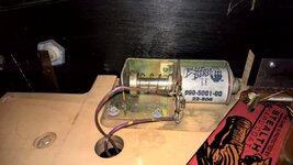
I tested the Laser Kick coil and Diode again, replaced PPB Q4 TIP36C again, and it appeared to work again for a bit. However if I exercise the Laser Kick in diagnostics it sticks on after about half a dozen times and Q4 is now toasted again (I guess then PPB F5 would blow if left on). I appreciate Laser Kick isn't used much in game - am I being unreasonable exercising the Coil in this way? I had two thoughts the 23-800 is bad, but it measures 4.5 Ohms which is per spec

23-800 D.E. REG 4R5 23 800

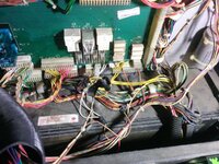
My other thought is that perhaps the TIP36C's are bad, they were cheap off Ebay. The upstream MPU Q24 driving transistor tests ok. In case I'm missing something obvious here's a photo of my nemesis;

WP_20150401_20_21_39_Pro.jpg

Other things all CPU Lamps still stuck ON and now I'm into Diagnostics Voice ROM 2 doesn't appear to work, the machine crackles when switch one when it should say 'Hook, Hook, Hook'. Voice ROM 1 ok I get some speech in game.
 
I tested the Laser Kick coil and Diode again, replaced PPB Q4 TIP36C again, and it appeared to work again for a bit. However if I exercise the Laser Kick in diagnostics it sticks on after about half a dozen times and Q4 is now toasted again (I guess then PPB F5 would blow if left on). I appreciate Laser Kick isn't used much in game - am I being unreasonable exercising the Coil in this way? I had two thoughts the 23-800 is bad, but it measures 4.5 Ohms which is per spec

Sounds like you need a new coil. I suspect it's fine when cool but if you warm it up with a few firings (so the coil windings expand slightly) then it shorts (and takes out Q4). You're not being unreasonable with exercising the coil, just think how many times a game the flipper coils get exercised.
 
Thanks @Moonraker was thinking much the same. There are several of those on the machine I'll try one from elsewhere. Also it was the ultimate solution to the similar thread on pinside from @Montu32 was experiencing, but his coil measurements were right out.

Any idea on all the CPU lamps being permanently on?
 
Are all the CPU lamps really bright? Do all of the controlled lamps have diodes accross them? The fact that all of the lights are permantely on sounds to me that you most likely have a board fault. Does the MPU have any signs of battery damage? The first thing I would do is test all of the transistors that control the lamp matrix are good. If all is well here (and by the sounds of it they could well be) then the problem will lie further upstream. I haven't looked at the schematic but my understanding is that Data East board sets were basically a clone of Williams System 11.

Following extensive repairs to my recently acquired Banzai Run due to battery damage including garbled display output, locked on coils, dead sound etc I have a gained a pretty good knowledge of the system 11 MPU. In my case all of the transistors were fine despite some of them having been locked on until fuses blew. The problem ended up being due to faulty 6821 PIA which in turn destroyed every other chip further down the chain until the first pre driver transistors. I think your problem could be something similar as you would be more than unlucky if every transistor controlling the matrix has failed.

If you haven't done so already I'd suggest having a little read of the troubleshooting guide here: http://techniek.flipperwinkel.nl/desega/index3.htm#lamp

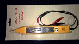
This is a good place to start from. You will need a logic probe to test that the chips are working as they are supposed to. Initially this stuff can be quite intimidating but if you have logical mind eventually you'll probably find it quite straight forward and its extremely satisfying when you finally crack it and restore everything to full working order, at least it was for me. :thumbs:
 
@aaronhicksuk I wouldn't say the lamp are excessively bright. To further explain my board is a Rottendog MPU004 so no battery to worry about and it looks relatively new. I've studied the guide you've referred to and with the machine in Diagnostics -> 'All Lamps' (so should flash but are still all on) have disconnected the lamp row and column connectors and tested across them with a croc clip, #555 bulb and diode (per the guide) at this point the bulb is on for every intersection of the matrix so not a PF problem I presume.

Coincidence that you suggest a logic probe as I have one on order to pickup tomorrow and that's my next move.
 
I was a little worried at first when you first mentioend an aftermarket board but as far as I can tell the Rottendog MPU004 is of through hole construction and not surface mount, which means repair should be possible. The test you have done with the diode, lamp and crocodile clips confirms you indeed have a board problem. There may be other issues on the playfield but until you have a working MPU you can't really find out what these are.

I generally find its best to start at the end of circuit and work backwards until you find the fault. Although its unlikely that all of the lamp matrix transistors have failed they are quick to test with a multimeter and well worth doing. My gut feeling is that you have a problem with one of the logic chips that drive these transistors. In turn this may have caused some of the transistors to fail too depending on how much abuse they have taken (probably not too much on a lamp matrix, more of a problem with coils.)

You also mention you have a problem with a locked on coil which is destroying transistors. I haven't looked at the schematic but this may not be unrelated to your lamp matrix fault as they may well be controlled by the same PIA. If a PIA is a common component to both problems then there is a stong likelyhood it is faulty. In the case of my Banzai Run one of the PIAs was responsible for a large portion of the garbled display logic and a pop bumper which was locked on.

You seem like you have a reasonably good idea on what your doing so I'm confident you'll get to the bottom of it. Let me know if you get stuck and I'll try and dig out a schematic and help you out the best I can.
 
@aaronhicksuk tbh it's this part of the hobby I enjoy, I don't even know what a logic probe is yet, but I'm looking forward to getting one and learning how to use it to diagnose problems further. This time last year I didn't own a DMM. I have the schematic for the Rottendog here http://rottendog.us/MPU004.pdf and the lamp col and row connectors (CN6 & 7) converge at a common 6821 PIA U11. I was just going to try swapping it over with one from my Gold Ball - but as its not socketed that's a bit of a faff.
 
Yea I enjoy the repair and refurbishment side of Pinball as well as playing too, to me they're just the ultimate indoor toy (motorcycles for outdoors, I fix them too!)

Changing 6821 PIAs isn't too bad providing you have half decent soldering equipment. Ideally you want a desoldering station as these make chips pretty easy to remove with out destroying either the chip or the board. The board traces on these are fine and you really can't afford to tear out any of the plated through holes. If the chip is properly desoldered it should more or less fall out of the board without force. Its worth checking that all of the legs are free to move. If this isn't the case don't be afraid to apply more solder and start on problem legs again. You use the solder to transfer heat through the whole joint and then suck the whole lot up in one move. With a desoldering station I find its good to wiggle the legs around with the nozzle to keep it from becoming stuck to the side of the through hole.

When going back together its important that you flow solder through the whole joint as the boards are double sided. If you apply heat for too long then you risk damaging the board but you shouldn't be too scared of it as you need the joint to be heated through for the solder to flow where it needs to be on both sides. Touching a small amount of solder on to the iron before starting helps to transfer heat to the leg, you can then apply solder from the opposite side of the joint to the iron and it should flow in and fill the void. Takes a little practice to get good but its not rocket science and not really that difficult. If you apply common sense its pretty hard to **** up boards entirely IMO, just be careful until you have confidence. Some of the work I've seen leads me to believe whoever did it would struggle to change a wheel on a car! Last but not least its documented absolutely everywhere but make sure you socket any chips you change.

How not to do it, its not as if the pads aren't big enough in this case!

IMG_20150208_183959.jpg IMG_20150208_193309.jpg
 
I would be annoyed if the MPU is faulty, although its a few years old. It was bought solely for Hook and has been in it since I bought the board.
Saying that I don't remember the GI being on all the time but it is possible, didnt even notice when i set it up for the pictures I sent you, doesnt mean it wasnt but I didnt notice (feel a bit stupid)

I have a few solenoids in my parts, I will look over the weekend and see if I have one suitable for the kickback and if I do Ill get it posted out to you..
 
Thanks @BigIan if you have got a spare 23-800 I'd appreciate it. No prob's regarding the MPU I'm confident it's fixable -it's the CPU lamps that are all stuck on, and defo the problem appears to be at the MPU level, probably a PIA or such like, I don't know yet but I'm learning this stuff fast.
 
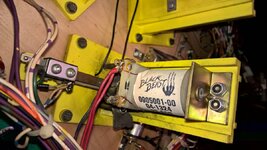
Good call @Moonraker swapped a 23-800 to the Laser Kick from one of the bumpers today, put on another new Q4 (lucky I bought x5) and so far so good. It exercised without blowing F5 and Q4 again!

Also, noticed whilst dismantling the bumper that on 2 of them the plastic retainer is broken - see below. So something else to add to my next Pinball Mania order.

Tried re-seating voice rom 2 to no avail. I notice this is the only ROM without the sticker covering the window, as Voice ROM 1 and all other music and sounds are working I'm assuming the sound card is good and have ordered a new ROM from @myPinballs who attended to this even though prepping for 8bitflip (added the latest custom Gold Ball ROMs whilst I was at it).

So this only leaves the CPU lamps stuck ON. I got the logic probe today but have timed out on that task.


WP_20150403_14_05_16_Pro.jpg
 
they're just the ultimate indoor toy (motorcycles for outdoors, I fix them too!)
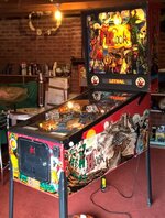
These hobbies seem to go together don't they, notice green covered item left of Hook, also re-chromed crash bar hanging from rafters.

WP_20150328_16_23_03_Pro - Copy.jpg
 
Just bagged myself a project Hook @astyy - we'll have to compare notes once I get it in the workshop!
 
Just read your thread from cover to cover. Good stuff and great detective work @astyy! I like your persistent attitude and willingness to dig deeper than you might know at the time. That's how you discover and learn stuff. And thanks to everyone els for all their helpful comments. This is Pinball Info at its best.
 
Just bagged myself a project Hook @astyy - we'll have to compare notes once I get it in the workshop!
Nice one @PeteB . Is it the one that was on sale here last week with the broken ship plastic? If not can you post some 'before' pic's so I can see what you're up against.

And thanks to everyone els for all their helpful comments.
Agreed @Nedreud defo good community support here, which bolsters confidence to proceed. @JWG9999 is a Hook owner too and has been answering my daft comparison questions between our machines in a separate PM.

I bought this thinking it was mainly to be a carpentry project, but so far concentrating on the game side and am getting there. Just got to diagnose these pesky stuck on CPU lights - am off to my workshop on that next.
 
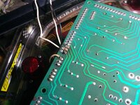
I picked this up yesterday to further t/shoot the stuck on CPU lamp matrix problem. With the machine in Diagnosis -> All Lamps Flash and then selected single lamps and in both cases CN7 switch column is testing pulsing (maybe ok), but CN6 switch row are testing permanently low- which would explain why they lamps are permanently on.

WP_20150404_12_37_43_Pro.jpg

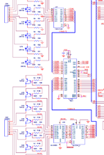
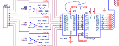
Here is the relevant part of the MPU schematic, I'm not entirely sure how to probe the 74HCT240 which is next upstream of CN6. With machine off I diode tested the address pins to the ground pins which appeared ok.

upload_2015-4-4_19-10-6.png
 
Excellent work so far @astyy , your're narrowing the problem down. I have the very same logic probe! :) When looking to test out an IC you first need to know what it is supposed to do, for which you need the datasheet: https://www.fairchildsemi.com/datasheets/MM/MM74HCT240.pdf

This tells us that the 74HCT240 is a "Inverting Octal 3 State Buffer" and explains in detail how the logic works and its operating characteristics. However, before you get too bogged down with logic/truth tables first check that the chip has a good power supply.(Especially as every single output is in question in your case.)

The schematic above doesn't show it but according to the data sheet the chip should have "VCC" (5V Power Supply) applied to pin 20 and be grounded on pin 10.

Pins 1 and 19 are "active low enables" and the schematic shows they should be permanently grounded. This makes things simple as all of the buffers should be enabled all of the time in this application. (If they were connected to lines that moved, if the line went high the 4 buffers controlled by each one would enter tri state mode. This is a posh way of saying the output should have high impedance, essentially removing it from the circuit.)

If the power supply to the IC looks fine then get the diagnostic mode to flash all the lamps, then probe the inputs to the chip on pins 2,4,6,8,11,13,15 and 17 as these should be moving between high and low.

The 74HCT240 is an inverting buffer, so if an input is high the corresponding output should be low and vice versa. If VCC and ground are good, the active low enables well grounded and inputs from the PIA moving but the outputs aren't then the chip is duff and should be replaced.

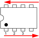
The pins on the chip are numbered anticlockwise from the notched end as shown in the picture below:

www.amiga_stuff.com_hardware_images_DIP_numbering.gif

Be careful when probing that you don't short across the legs, its easy to blow stuff up if you do (to be expected!) I proved this theory personally when fixing my Banzai Run soundboard after shorting VCC to an input on the YM3012 (DAC for the YM2151 synthesis chip) It made a loud hum and then was completely ****ed! :rolleyes: Luckily already socketed and an easy change with nothing else broken.
 
Last edited:
Ah I also forgot to mention its not a good idea to probe things that you can expect to see a high voltage on (e.g. more than 5V logic) as you could damage your probe. The lamp columns are at 18V which isn't massive but still not ideal. If this was a 75V coil output you may be in real trouble! Better to probe the outputs on the ULN2803 @ U19 in this case if the outputs were suspect.

Most of the time coil outputs are slow moving so you can use a multimeter. If you want to look at really fast moving high voltage outputs you really need something meatier like an Oscilloscope, however this really isn't necessary for most things pinball.
 
@aaronhicksuk this is the type of techie post I really like - later I can excuse myself from Easter lunch as I have an
"Inverting Octal 3 State Buffer"
to probe!

I took the MPU out yesterday to check all connectors and inspect the tracks & general condition. As @BigIan says above, its like new and no obvious nicks, blemishes or damage. Looking at the ICs I'm not sure I fancy replacing a 20 or 40 pin socketed component the soldering work is extremely fine - I'll build up to that.

One minor query ...
Better to probe the outputs on the ULN2803 @ U19 in this case
At this point aren't the outputs already at 18VDC per pin 10
 
Sorry yea you're right, the outputs of that chip are already at 18v. I didn't look close enough at that bit and it was early in the morning when I wrote that!:rolleyes:

To be honest you'll be ok to probe 18v anyway. I just found a PDF here which says the impedance of the probe is 1M Ohm and it can handle up to 220v for 15 seconds! https://www.google.co.uk/url?sa=t&s...C4nhg1RzYA0enIebQ&sig2=Lhj6SWOekSSxp3Oq3z-jHg Not all probes necessarily can though and if I'm honest I wouldn't want to be probing voltages like that with what is ultimately some cheap Chinese piece of **** lol! I'll use my Fluke for stuff like that thanks, got a feeling I'll live longer that way.

So yea probe away at the lamp stuff all you want in that case. What you'll find though is most of the time stuff tends to lock on or doesn't work at all so using a DMM tells you all you need to know and is safer.
 
Nice to know the board looks in good condition overall. What you're really looking for first of all is a fractured joint or such like. The fault could be really simple like the chip not getting power etc. If this is the case you don't even need to remove it, just reflow solder on the affected pin/s.

Removing chips isn't that bad but you really need the right tools to do it properly, in other words a desoldering station. If you don't have one and you are certain a chip is faulty then the safest thing to do is cut the legs and then poke them through one at a time with a hot iron, then clean the through holes out with a pump.

There's only one way to get good at anything and that's get stuck in. Most stuff is surface mount these days unfortunately so its hard to find duff stuff to practice technique on.
 
If the power supply to the IC looks fine then get the diagnostic mode to flash all the lamps, then probe the inputs to the chip on pins 2,4,6,8,11,13,15 and 17 as these should be moving between high and low.

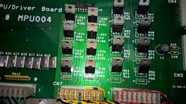
The 5V on U21 tested good, as did the 3 grounds, inputs all strobing and outputs when in 'All Lamps' mode. This leads me back to the bank of row transistors Q72 - Q79, could they all be bad I've tested them all several times. However, I've spotted something odd Q72-Q79 lamp row drivers should be 20N10L and Q64-Q71 lamp column drivers TIP107. However on close inspection both banks of transistors are marked TIP107! The schematic for each type of transistor looks very different, perhaps this is the fault and wrong from new? The board uses lots of 20N10L (actually 13N10L installed) elsewhere and TO-220 case so not easy to spot at first.

Here is a close up where you can see the markings on several. I read online that an IRL540N is the modern upgraded equivalent for a 20N10L. Hopefully another major problem sorted with this machine.

WP_20150405_14_08_54_Pro.jpg
 
Last edited:
Wasn't this board supposed to work before? You say it doesn't look like they have been ever changed? You're right in saying the transistors don't seem right. The 20N10L is a N channel MOSFET transistor, kind of a MOSFET equivalent of a bipolar NPN transistor like a TIP102. The main reason the symbols look so different on the schematic is one is a MOSFET and the other BJT. The direction of the small arrow denotes whether it is PNP or NPN.

Do you have any transistors you can change in?
 
The CPU lamps haven't worked since I took-over the machine a couple of weeks ago from @BigIan, he bought this MPU new for the Hook but I think it was stored so perhaps its never worked. I'm wondering if this is what we used to call a 'Friday afternoon car' and the TIP107's were fitted throughout by mistake when assembled.

It would be good to swap-over to test, I def don't have any 20N10L or 13N10L - let me check what I have.
 
Fair enough, if its never been seen working then you've found your problem. Nice easy fix really. :)

Absolutely shocking QA from Rottendog if they let that slip through without noticing. You'd think that would of shown up on a test rig for sure.

Things like that just add more reasons why I'd rather repair a broken original rather than use an aftermarket. They should just rename themselves Rotton Amusements lol.
 
Be careful when probing that you don't short across the legs,
I think I may have done that probing U19, I noticed a lamp column out yesterday and now its blowing one of the T8A fuses next to the BRs and all CPU lamps are off as no 18V to the MPU. U19 ping 13 is grounded unlike the others.

U19 is a ULN2803 which appear to be readily available on eBay.

Should I replace this socketed? Are all the components and sockets born equal e.g.
http://www.ebay.co.uk/itm/Standard-...20-22-24-28-32-40-Pin-IC-Socket-/231355183099
http://www.ebay.co.uk/itm/20-PCS-UL...-DARLINGTON-ARRAYS-IC-SOCKET-UK-/400620244795

Thanks.
 
Back
Top Bottom