What's new
Pinball info

Register a free account today to become a member! Once signed in, you'll be able to participate on this site by adding your own topics and posts, as well as connect with other members through your own private inbox!

In Progress Hook, line and sinkered...

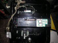
that pcb near the pendulum tilt (with a chip labelled 'Zenitone Limited) is probably a 'credit board',

Interesting, and nedrued pointed out there is a mechanical counter fitted too. What I haven't found in this area is the knocker which is of interest as that is in the group of solenoids connected to the PPB F5 fuse which is blowing.
 
I'm sure I once saw some cabinet decals somewhere but can't find them again now. Maybe you will have to just touch it up. Luckily there's a lot of red areas so it shouldn't be too hard. :)
 
What I haven't found in this area is the knocker which is of interest as that is in the group of solenoids connected to the PPB F5 fuse which is blowing.

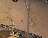
Well you don't have to find the knocker... (I trust you have checked the top corners of the back box...?)

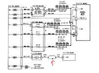
Page 29 (&45) of the manual (33/95 &50/95 in the pdf) shows J2 Pin 1 (WHT-GRY) of PPB Board Feeding pin 1 of J8 (goes to Q5). Pin 2 of J8 (VIO-GRY) feeding the knocker coil with the other side feeding J7 pin8 (YEL-VIO) of PPB Board. So you can check coil resistance between pin 2 of J8 and pin 8 of J7.

You could also take the PPB board out and test every transistor on there with your meter.
http://www.pinwiki.com/wiki/index.php?title=Data_East/Sega#Driver_Transistor_.22Quick_Check.22
 
Reviewing my photos above of inside the cabinet - I think this is where the knocker should be. Colours as per your description above and what looks like the 3 holes for the bracket.
 
Yep, that should terminate at the knocker. So it's missing from your game and is unlikely to be the cause of the fuse blowing.... :cool:
 
Made some good progress last night. Fitted the proper fuses to the flipper PCB. Soldered all the obvious loose cables I've found so far (flipper, backbox, speaker etc). Powered up the machine with PPB J8 disconnected and flippers are now working.

Then took @Moonraker advice and measured resistance between pins on PPB J7 and J8. After some testing I disconnected the Brown/Violet cable to Solenoiid on the left Outlane - Laser kick? - (cables Violet/Yellow to Brown/Violet). With this disconnected and PPB J7 re-inserted the machine boots and doesn't blow PPB F5. The Brown/Violet cable appears to be permanently earthed and when I temp earth this coil it fires.

So I'm assuming we're next into testing the transistors on the PPB and CPU. From the below I can see it goes to PPB Q4 (TIP36C) then to CPU Q24 - I have a Rottendog MPU004 so the 20N10L at the same location.

upload_2015-3-25_7-23-21.png
 
Last edited:
that pcb near the pendulum tilt (with a chip labelled 'Zenitone Limited) is probably a 'credit board', which would take over the pricing arrangements. The installation looks disticntly post-factory.
I thought the same and i'm pretty sure it's not how it would have been at the factory. My R&B has a similar credit board but mine is located right near the coin mech, as shown below.

2014-07-22 22.08.13.jpg
 
Yep looks like Q4 (or Q24) is blown. You're back to taking the PPB board out and testing Q4 and Q5 transistors. If Q4 is blown and Q5 is ok then remove Q4 and replace with a new one or with Q5 if you don't have any new ones.
 
or with Q5 if you don't have any

I like your thinking Q5 is for the awol knocker then (which I will replace at some point) I have some TIP36C's for the PPB on order and if its MPU Q24 that's a 20N10L which I read can be replaced with a better IRL540N.

What I'm not sure of is Clays talks about a further 2N4401 pre-driver to Q24 etc on the original DE MPU - are these not used on Rottendog MPU004?
 
It's almost certainly Q4 that's toast, Q24 will probably be ok. Using Q5 will help confirm it (providing Q5 is ok). I wouldn't worry about Q24 for now.
 
Great will test this later. As a matter of interest, why is this Solenoid on its own 50V feed and not sharing the common one to the other 50V coils? The others are multiplexed with lamps whilst this one is continuous power for some reason.
 
Last edited:
A solenoid such as an outlane kick-back could be needed at any moment, so I suppose this is why DE elected to drive it from one of the non-multiplexed/extended solenoid assignments. If there was flashbulb activity going on at the instant the outlane switch was detected, even the delay turning off the multiplex/extender relay might well result in the kick-back firing too late. Williams took the same view; F-14 has two kick-backs, both controlled from non-extended assignments. Even with the only game I know of using solenoids on the extended side (Road Kings), the solenoids concerned aren't 'instant' response ones.
 
It's almost certainly Q4 that's toast, Q24 will probably be ok. Using Q5 will help confirm it (providing Q5 is ok).

I tested the PPB Q1-5 TIP36c's last night and Q4 certainly tested bad. What was strange is that when I first tested them Q5 was withing range of appx 0.5V on both outer legs, but Q1-4 all appeared bad 0.01V or similar. After I'd powered it up and investigated a few other bits I came back to test again and then Q1-3 and Q5 were within range and Q4 still bad - very strange. I didn't try swapping Q4 & 5 as I want to replace the diode on the coil and I'm waiting delivery on these and some TIP36c.

I'm not used to the diagnostics i/f yet and this is seemingly reporting some other problems. The bottom trace of GI on the backbox is out. I'll fix what is obviously wrong in order as then its easier to highlight the next problem and check they're not related.
 
The bottom trace of GI on the backbox is out. I'll fix what is obviously wrong in order as then its easier to highlight the next problem and check they're not related.

GI is a totally separate circuit and it's not related.
 
Last edited:
I have no 6.3VAC to the bottom string of the GI on the BB (white brown/brown) I've traced this via PPB J5 5 to Fuse F4 which is good. Can you give me some pointers on t/shooting this further?

Edit

Lazy me I should have Googled,
https://groups.google.com/forum/#!topic/rec.games.pinball/Qr6qEebpsiE

Not sure if that forum sorted out your problem but I've just had to fix the GI on my Time Machine and it doesn't look like there's much difference:

GI lighting power comes off Power Supply at CN8 so test here first. The GI lighting circuit doesn't do much else, it goes through PPB board fuses and then off to Backbox and Playfield, so if the power supply is delivering OK, and the PPB fuses are OK, then the PPB connectors are almost certainly the problem.

Or so says the guy (me) who didn't understand electrical stuff at school o_O
 
Not sure if that forum sorted out your problem

Thanks for your advice - I've literally just discovered a continuity break between PPB CN8 Pin 1 and the F4 Fuse Holder. What threw me is that the wiring to the bottom GI uses white/brown - brown and I have to get the PPB off to replace TIP36C Q4 for another problem and that has a white/brown cable connected too which obviously heads elsewhere. Did seem a coincidence though.

When my parts arrive and I hit the PPB should be able to fix both problems in one go. Its only held on by a few bolts and flexing all over the shop, I need to get the proper bolts and get all of the PCBs secured and back plane secured..
 
Good progress to report this weekend.

BB bottom GI string now working, path PPB CN8 Pin 1 to Fuse was indeed open, re-flowed pins on CN8 and all was good. A couple of #44 holders are bad that need replacing.

For PPB F5 blowing and Laser Kick sticking on I replaced PPB Q4 and the 1N4004 across the coil. This initially seemed to work but then the flippers started activating the Laser Kick coil (weird) and it fused again. Today I replaced PPB Q4 again and its associated diode D18 and I tested the Q3 associated diode D19 was bad so replaced that (coil diode still good). Since switching it on it has worked ok and played a few games at last.

What is o/s, (and maybe related) is that Diagnostics is reporting Right Flipper SW ON, I'm not familiar with DE diagnostics but all the options wizz through which I'm guessing is cos the flipper selects them? I've traced the flipper SW wires back to the Flipper PCB and the switch is certainly not closed and plays fine in game - any ideas on this one guys?
 
Last edited:
For those who like it in pictures.

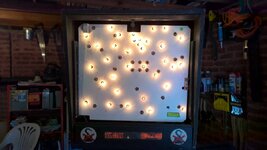
PPB CN8 re-flowed we have lights. A couple of lamp holders need replacing and Twinkerbell needs sorting.

WP_20150328_11_34_07_Pro.jpg

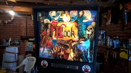
Backglass cut (that's another story) its looking more like a pin (note key in lock as the glass is too big). This picture reminds me their is a gap each side of the DMD housing - is this normal?

WP_20150328_12_03_05_Pro.jpg

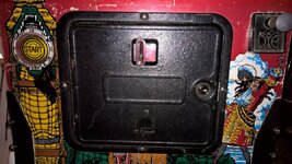
Coin door swinging open was doing my head in so fitted a lock

WP_20150328_14_47_00_Pro.jpg

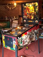
Got it on its legs for the first time, I had no idea they are so much taller than an 80s Bally. Then Mr Muscled the glass so I could see through it, then got a few games in - woo hoo!

WP_20150328_16_23_03_Pro - Copy.jpg

Hopefully I can get this flipper switch problem sorted and move on to making it look nicer.
 
What is o/s, (and maybe related) is that Diagnostics is reporting Right Flipper SW ON, I'm not familiar with DE diagnostics but all the options wizz through which I'm guessing is cos the flipper selects them? I've traced the flipper SW wires back to the Flipper PCB and the switch is certainly not closed and plays fine in game - any ideas on this one guys?

Remove the balls and lift the playfield up and see if the leds on the flipper PCB in the cabinet light correctly when the flipper buttons are pressed.
 
Will do @Moonraker. Are the flipper buttons used within the Diagnostics? I scroll through the categories and things like the sound tests just wizz by, I can scroll through the lamp tests using the Credit button but don't see any difference when I select the Rows & Columns.
 
Will do @Moonraker. Are the flipper buttons used within the Diagnostics? I scroll through the categories and things like the sound tests just wizz by, I can scroll through the lamp tests using the Credit button but don't see any difference when I select the Rows & Columns.

Do you mean for switches ? Take the playfield glass off and try activating a switch...
 
Remove the balls and lift the playfield up and see if the leds on the flipper PCB in the cabinet light correctly when the flipper buttons are pressed.

When in game or diagnostics Right Flipper lights LED L1 and Left Flipper lights L2. They turn off as soon as the flipper is released.

However, I'm pretty much back to where I started on Friday - the Laser Kick coil stuck on again - PPB F5 blew and then after that the Flippers activate Laser Kick in a weak kind of way. I haven't checked yet but I'm guessing PPB Q4 is toast again as I've replaced F5 de-soldered the Laser Kick and its permanently grounded again.

But, what I've noticed and I think my confusion in the Diagnostics is that the Feature Lamps aren't working at all they appear to be permanently ON when in diagnostics or in game. Hence when I scroll through lamp rows, columns and individual lamps I see no difference the playfield is near permanently lit. The flashers appear to be working which detracted me from it.
 
Now that you say about the outline kickback firing when the flippers are pushed I remember that happening before. I think it just stopped though (might have reseated the cables or something easy, nothing complicated )

I guess it was only a temporary fix though.
 
@BigIan was that recently or when you used to play it? I'm trying to work out what is faulty caused by the long term storage.

I had a mate over this afternoon who is good with electronics. One small victory, the back of the PF GI was out and we traced this back to a bad connector on the PPB so that is all looking better.

Regarding the more significant problem of the feature lamps all being permanently lit. We tested the 18VDC on the MPU Board (Rottendog) and found only 14VDC. We ran out of time but my mate was suspecting the big blue Cap mounted to the BB and possibly replacing BR1 and BR2 as a matter of course which appear to be working but are well corroded. We tested the output across these and the 18VDC was lower than expected (BR1 I think).

Could this low voltage be the root cause?

Not sure if this is related oto the F5/Laser Kick/Flipper SW stuck problem but may as well fix what is obviously bust.
 
It was a few years ago, I had forgotten about it until I read it up there and it sounded very familiar, from memory it was only when you push the right flipper button ?
 
Back
Top Bottom