And would you Adam and Eve it!! There's a paragon pf on eBay !! Starting bid £95!!
Pinball info
You are using an out of date browser. It may not display this or other websites correctly.
You should upgrade or use an alternative browser.
You should upgrade or use an alternative browser.
In Progress Adventures in Budget Restoration: 1978 Bally PARAGON
- Thread starter Nedreud
- Start date
Just for the record:
http://r.ebay.com/3wUImt
How tempting is that? Hard to see the exact condition from the photo but I don't see any obvious wear, especially around the 1 to 10 bonus triangle of inserts. I wonder how much it'll go for?
http://r.ebay.com/3wUImt
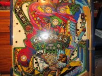
PARAGON BALLY PINBALL PLAYFIELD- AMAZING PAUL FARIS ARTWORK
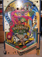
Starting bid: £95.00
This auction is for the PARAGON BALLY PINBALL PLAYFIELD, this is just the playfield NOT a full machine. The playfield is in excellent condition and can be used to re-furbish an existing Paragon Pinball or just as a decorative artwork feature on a wall (or like).
Please take a look at my other auctions for TWO Paragon Pinball Machines one being the rare European model.
Obviously this is for CASH ON COLLECTION only.
How tempting is that? Hard to see the exact condition from the photo but I don't see any obvious wear, especially around the 1 to 10 bonus triangle of inserts. I wonder how much it'll go for?
There's a couple of complete tables on eBay at the moment too.
http://www.ebay.co.uk/itm/PARAGON-P...eo_Games_Coin_Operated_MJ&hash=item2a33412b7b
http://www.ebay.co.uk/itm/PARAGON-W...eo_Games_Coin_Operated_MJ&hash=item2a33414bb5
Be interesting to see what they go for.
http://www.ebay.co.uk/itm/PARAGON-P...eo_Games_Coin_Operated_MJ&hash=item2a33412b7b
http://www.ebay.co.uk/itm/PARAGON-W...eo_Games_Coin_Operated_MJ&hash=item2a33414bb5
Be interesting to see what they go for.
May-June 2013
BITS'N'BOBS
Another little jumbled selection of things!
A little international eBay purchase from the USA: a pair of brand-new reproduction old-school mini-flippers. Total cost just under £13 ($21). I only need one left-hand "FLIPPER" which sits half way up the playfield by the entrance to the VALLEY OF DEMONS:
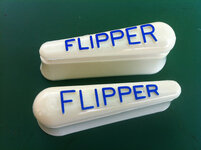
Paragon: New mini-flippers by staticboy, on Flickr
On my machine this had been replaced with an incorrect transparent red mini-flipper:
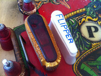
Paragon: New mini-flippers by staticboy, on Flickr
A member of the ukpinball Yahoo Group contacted me to see if I needed any Paragon spares, but I already had what he was offering. But after a chat he ended up giving me the remnants of a very rotten Paragon playfield which had been stored and left to rot in a shipping container for years. Such a sad sight as it had been in better condition than my playfield but thought there would be a few salvageable parts as it was was still fully-populated on the underside:
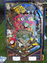
Paragon: Donor playfield (topside) by staticboy, on Flickr
He also gave me a big bag of star posts and a bunch of parts to fix my missing pop bumper:
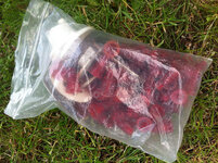
Paragon: Spare star posts by staticboy, on Flickr
One of the other small temporary jobs I did was to fit a lock onto the coin door. I was going to leave this last as a sort of ceremonial final act of completion but I got fed up with the door always swinging open!
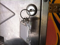
Paragon: New coin door lock by staticboy, on Flickr
I also borrowed a polishing tumbler from a friend (a Lyman Turbo PRO 1200). Here's the result of tumbling a random selection of fairly grotty parts:
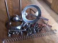
Paragon: Tumbler test batch by staticboy, on Flickr
Some parts better than others. The lamp holder from a pop bumper just ended up caked in red rouge as did most of the screws - they'll be easier to buff on the polishing wheel. But parts like the pop bumper rings, tilt ball and springs all showed a massive improvement. I'll definitely be borrowing it again!
BITS'N'BOBS
Another little jumbled selection of things!
A little international eBay purchase from the USA: a pair of brand-new reproduction old-school mini-flippers. Total cost just under £13 ($21). I only need one left-hand "FLIPPER" which sits half way up the playfield by the entrance to the VALLEY OF DEMONS:

Paragon: New mini-flippers by staticboy, on Flickr
On my machine this had been replaced with an incorrect transparent red mini-flipper:

Paragon: New mini-flippers by staticboy, on Flickr
A member of the ukpinball Yahoo Group contacted me to see if I needed any Paragon spares, but I already had what he was offering. But after a chat he ended up giving me the remnants of a very rotten Paragon playfield which had been stored and left to rot in a shipping container for years. Such a sad sight as it had been in better condition than my playfield but thought there would be a few salvageable parts as it was was still fully-populated on the underside:

Paragon: Donor playfield (topside) by staticboy, on Flickr
He also gave me a big bag of star posts and a bunch of parts to fix my missing pop bumper:

Paragon: Spare star posts by staticboy, on Flickr
One of the other small temporary jobs I did was to fit a lock onto the coin door. I was going to leave this last as a sort of ceremonial final act of completion but I got fed up with the door always swinging open!

Paragon: New coin door lock by staticboy, on Flickr
I also borrowed a polishing tumbler from a friend (a Lyman Turbo PRO 1200). Here's the result of tumbling a random selection of fairly grotty parts:

Paragon: Tumbler test batch by staticboy, on Flickr
Some parts better than others. The lamp holder from a pop bumper just ended up caked in red rouge as did most of the screws - they'll be easier to buff on the polishing wheel. But parts like the pop bumper rings, tilt ball and springs all showed a massive improvement. I'll definitely be borrowing it again!
A
abaxas
Ultrasonic cleaner time?
Gets to the parts other cleaners cannot reach.
Gets to the parts other cleaners cannot reach.
What cleaner do u put in the ultrasonic cleaners?
A
abaxas
I bought an ultra cheapo ebay jobby for 18 quid. It's poor but with time it gets parts clean but not shiney.
I use three chemicals concoctions, depending on what I want to do.
1) citric acid (or lemon juice) for rust removal
2) small amount of dishwasher powder (less than you think!)
3) Generic cheapo washing up liquid.
I then rinse under the tap and put all the parts in a fan oven set to 50c.
I use three chemicals concoctions, depending on what I want to do.
1) citric acid (or lemon juice) for rust removal
2) small amount of dishwasher powder (less than you think!)
3) Generic cheapo washing up liquid.
I then rinse under the tap and put all the parts in a fan oven set to 50c.
A
abaxas
I'm sure proper solution is better, but this works and cleans things faster than I take them off the machine 
Could you provide a link or picture of the cleaner (or similar) you got from eBay? I just did a search and there are literally hundreds to choose between!I bought an ultra cheapo ebay jobby for 18 quid
A
abaxas
http://www.ebay.co.uk/itm/Ultrasoni...ewelleryBoxes_Supplies_CA&hash=item19e2a0c084
But cost 18 quid.
Works as well as it costs! But does get things clean.
But cost 18 quid.
Works as well as it costs! But does get things clean.
September 2013
PLAYFIELD STRIPDOWN
I didn't get much done during July, August and most of September (school holiday and birthdays, etc.) but late September I started to strip the playfield.
I started with the topside with the playfield still inside the cabinet. After taking off the obvious top layer of accessories, such as plastics and bumper caps, I set about taking dozens of reference photos so I know how it all goes back together. I took apart each area/feature one at a time, taking lots of photos and keeping all the parts, nuts, bolts, screws, posts and gates in clearly labelled zip-bags:
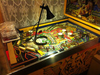
Paragon: Playfield Stripdown by staticboy, on Flickr
A few interesting things turned up. Paragon seems to make use of quite a few nails here and there, such as these in the slingshots:
Paragon: Strip-down reference photos by staticboy, on Flickr
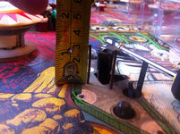
Measuring the height of wire guides:
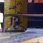
Paragon: Strip-down reference photos by staticboy, on Flickr
Some restoration guides note that wire guides can have crimped or knurled ends which can split the wood when removed. I can confirm this is not the case on PARAGON. In fact, the wire guides were easily removed pulling by hand so no concerns denting the surface using a lever (not that the surface of my playfield is worth protecting):
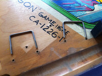
Paragon: Playfield Stripdown by staticboy, on Flickr
The trade-mark Greg Kmiec solid-red post supporting the spinner arch. See http://www.jeff-z.com/pinball/redpost/redpost.html for what this is all about!
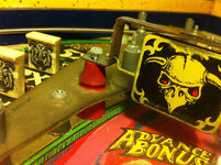
Paragon: Playfield Stripdown by staticboy, on Flickr
The troublesome plastic deflector and metal deadening plate for the TREASURE CHAMBER saucer. Again, another interesting little tale for all you design nerds out there: http://mirror2.ipdb.org/files/1755/...g_Kmiec_Discusses_Treasure_Chamber_Design.pdf
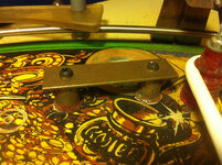
Paragon: Playfield Stripdown by staticboy, on Flickr
Registration marks for the various screen print colours showing just how far out some of the layers can be. That pink is off by nearly 3mm both horizontally and vertically. This is what leads to some interesting edge effects where the different colours overlap by a noticeable amount when they shouldn't.
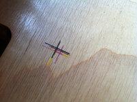
Paragon: Playfield Details by staticboy, on Flickr
Oops! I guess I need to update the title of my Shop Log:
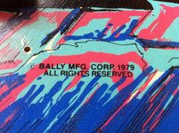
Paragon: Playfield Details by staticboy, on Flickr
PLAYFIELD STRIPDOWN
I didn't get much done during July, August and most of September (school holiday and birthdays, etc.) but late September I started to strip the playfield.
I started with the topside with the playfield still inside the cabinet. After taking off the obvious top layer of accessories, such as plastics and bumper caps, I set about taking dozens of reference photos so I know how it all goes back together. I took apart each area/feature one at a time, taking lots of photos and keeping all the parts, nuts, bolts, screws, posts and gates in clearly labelled zip-bags:

Paragon: Playfield Stripdown by staticboy, on Flickr
A few interesting things turned up. Paragon seems to make use of quite a few nails here and there, such as these in the slingshots:

Paragon: Strip-down reference photos by staticboy, on Flickr
Measuring the height of wire guides:

Paragon: Strip-down reference photos by staticboy, on Flickr
Some restoration guides note that wire guides can have crimped or knurled ends which can split the wood when removed. I can confirm this is not the case on PARAGON. In fact, the wire guides were easily removed pulling by hand so no concerns denting the surface using a lever (not that the surface of my playfield is worth protecting):

Paragon: Playfield Stripdown by staticboy, on Flickr
The trade-mark Greg Kmiec solid-red post supporting the spinner arch. See http://www.jeff-z.com/pinball/redpost/redpost.html for what this is all about!

Paragon: Playfield Stripdown by staticboy, on Flickr
The troublesome plastic deflector and metal deadening plate for the TREASURE CHAMBER saucer. Again, another interesting little tale for all you design nerds out there: http://mirror2.ipdb.org/files/1755/...g_Kmiec_Discusses_Treasure_Chamber_Design.pdf

Paragon: Playfield Stripdown by staticboy, on Flickr
Registration marks for the various screen print colours showing just how far out some of the layers can be. That pink is off by nearly 3mm both horizontally and vertically. This is what leads to some interesting edge effects where the different colours overlap by a noticeable amount when they shouldn't.

Paragon: Playfield Details by staticboy, on Flickr
Oops! I guess I need to update the title of my Shop Log:

Paragon: Playfield Details by staticboy, on Flickr
October 2013
BACKBOX STRIPDOWN
Time to start taking this bad-boy apart:
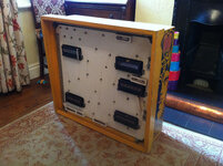
Paragon: Backbox Stripdown by staticboy, on Flickr
Again, clear labelling and lots of reference photos as I take things apart, this time unsoldering the wiring loom for the GI and indicator lamps:
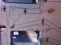
Paragon: Backbox Stripdown by staticboy, on Flickr
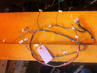
Paragon: Backbox Stripdown by staticboy, on Flickr
Next, time to pick off the wiring and lamp holders. This was a slow process as everything is just stapled onto the board! My preference will be to keep the existing wiring:
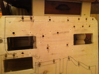
Paragon: Backbox Stripdown by staticboy, on Flickr
Then a quick repair using a liberal application of EVO-STIK Wood PVA to this small piece which I think is a light shield for the "MATCH" indicator on the backglass but makes a very handy handle when opening and closing the inner door (which is probably why it snapped off):
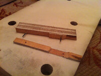
Paragon: Backbox Stripdown by staticboy, on Flickr
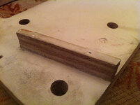
Paragon: Backbox Stripdown by staticboy, on Flickr
Then onto the sanding. For this I hit it with my evil belt sander fitted with 180 grit. Took all of 2-3 minutes to cut the original paint/primer back to the wood (it took a lot longer to do all the holes and fiddly bits in between by hand):
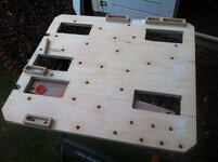
Paragon: Illumination board sanding by staticboy, on Flickr
After sanding there were several areas where the surface layer of ply had come away (caused by the rather rough and forceful drilling of holes). These areas were filled with Polycell Polyfilla Trade One Fill. I love this stuff. It's sold as a "trade" product and is so easy to use. Has the consistency of cream cheese but light as a feather. Dries very quickly when thin, even over-paintable in 15 minutes! And pretty tough too. I wouldn't use it to rebuild cabinet corners but it's fine everywhere else:
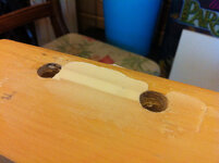
Paragon: Illumination Board Filler by staticboy, on Flickr
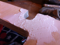
Paragon: Illumination Board Filler by staticboy, on Flickr
After more sanding with finer grit and a wipe down with tack rag and alcohol it was time to put on the first coat of combination primer/undercoat. I'll do 3 to 4 coats with a light sand between each followed by 2 coats of pure satin white for maximum reflectivity:
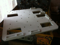
Paragon: Illumination board primed by staticboy, on Flickr
BACKBOX STRIPDOWN
Time to start taking this bad-boy apart:

Paragon: Backbox Stripdown by staticboy, on Flickr
Again, clear labelling and lots of reference photos as I take things apart, this time unsoldering the wiring loom for the GI and indicator lamps:

Paragon: Backbox Stripdown by staticboy, on Flickr

Paragon: Backbox Stripdown by staticboy, on Flickr
Next, time to pick off the wiring and lamp holders. This was a slow process as everything is just stapled onto the board! My preference will be to keep the existing wiring:

Paragon: Backbox Stripdown by staticboy, on Flickr
Then a quick repair using a liberal application of EVO-STIK Wood PVA to this small piece which I think is a light shield for the "MATCH" indicator on the backglass but makes a very handy handle when opening and closing the inner door (which is probably why it snapped off):

Paragon: Backbox Stripdown by staticboy, on Flickr

Paragon: Backbox Stripdown by staticboy, on Flickr
Then onto the sanding. For this I hit it with my evil belt sander fitted with 180 grit. Took all of 2-3 minutes to cut the original paint/primer back to the wood (it took a lot longer to do all the holes and fiddly bits in between by hand):

Paragon: Illumination board sanding by staticboy, on Flickr
After sanding there were several areas where the surface layer of ply had come away (caused by the rather rough and forceful drilling of holes). These areas were filled with Polycell Polyfilla Trade One Fill. I love this stuff. It's sold as a "trade" product and is so easy to use. Has the consistency of cream cheese but light as a feather. Dries very quickly when thin, even over-paintable in 15 minutes! And pretty tough too. I wouldn't use it to rebuild cabinet corners but it's fine everywhere else:

Paragon: Illumination Board Filler by staticboy, on Flickr

Paragon: Illumination Board Filler by staticboy, on Flickr
After more sanding with finer grit and a wipe down with tack rag and alcohol it was time to put on the first coat of combination primer/undercoat. I'll do 3 to 4 coats with a light sand between each followed by 2 coats of pure satin white for maximum reflectivity:

Paragon: Illumination board primed by staticboy, on Flickr
Looking good
Nice work.
Did you end up going for that Paragon playfield on eBay in the end? I noticed one of them sold for £95 with only a single bidder I recall.
I considered it very carefully. I was very tempted. But after studying the pictures closely (and higher resolution would have been better but the pictures added later were better than the original image on the eBay listing) I decided there would still have been a lot of work to do. There were several fairly large nicks, a track of wear on the main launch orbit just as bad as mine, and lots of inserts had their black ring worn to the wood. Nowhere near as bad as mine but for me it didn't justify the price and wouldn't qualify as part of my "budget" restoration.
I may yet come to regret my decision. Who knows?
The same seller was also parting with two Paragon machines, one US and the other a European 3-flipper model. He got £465 and £316 respectively. Not bad considering the US one had two duff displays and a dodgy sound board, and the Euro version didn't even have an MPU! Listing states new MPUs can be bought for $130 but an Alltek is $200.
Judging by those prices my Paragon has already broken the £500 value barrier as it's got a working MPU, rebuilt PSU, flawless sound, five faultless displays with the rest of it in pretty much the same condition
Re. the small flipper; you'll probably need a baseplate and shaft to mount the new white flipper on. Those transparent red ones usually have the flipper paddle moulded directly onto the shaft, with no baseplate.
Thanks for the tip-off, Jay. I wouldn't have discovered that until the day I re-built that flipper. At least I can now get on in advance.Re. the small flipper; you'll probably need a baseplate and shaft to mount the new white flipper on. Those transparent red ones usually have the flipper paddle moulded directly onto the shaft, with no baseplate.
October 2013
BACKBOX STRIPDOWN cont.
One of the more tedious jobs on my list... cleaning the lamp holders for the backbox GI. For some reason they all look like this, covered in a white powdery oxidation:
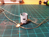
Paragon: Backbox GI chain by staticboy, on Flickr
As this is a budget restoration I can't possibly justify spending £1.20 replacing each holder when there are 40 of them in the backbox alone (grand total £48.00). If any are unserviceable then I'll replace them. It's another hot potato of debate on various pinball boards with good arguments on both sides of the restore or replace camps.
One common problem seems to be getting a good contact between the spring and the brass rivet at the bottom. One suggestion is to permanently fix the spring in place with solder. And re-oxidation after cleaning can cause issues but I'm sure some switch cleaner will help with that as it prevents as well as removes oxidation. Only time will tell but I ain't rushing to blow half a ton on ruddy bulb holders just yet!
Each holder takes about 2-3 minutes work with my copy Dremel mini-tool, first with a steel brush for the outside and then a sanding drum for the inside. By fitting the sanding drum proud of the holder the hollow end clears the spring on the inside so I can clean right down inside and not fudge the spring:
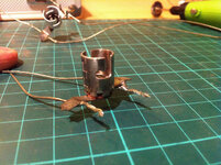
Paragon: Backbox GI chain by staticboy, on Flickr
Here you can clearly see the bottom of the contact spring sitting in its brass rivet. The sockets cleaned up really nice! I bet the current flow to the bulbs has been significantly improved after removing all the crud!
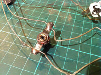
Paragon: Backbox GI chain by staticboy, on Flickr
Only another 35 to go... [YAWN]
BACKBOX STRIPDOWN cont.
One of the more tedious jobs on my list... cleaning the lamp holders for the backbox GI. For some reason they all look like this, covered in a white powdery oxidation:

Paragon: Backbox GI chain by staticboy, on Flickr
As this is a budget restoration I can't possibly justify spending £1.20 replacing each holder when there are 40 of them in the backbox alone (grand total £48.00). If any are unserviceable then I'll replace them. It's another hot potato of debate on various pinball boards with good arguments on both sides of the restore or replace camps.
One common problem seems to be getting a good contact between the spring and the brass rivet at the bottom. One suggestion is to permanently fix the spring in place with solder. And re-oxidation after cleaning can cause issues but I'm sure some switch cleaner will help with that as it prevents as well as removes oxidation. Only time will tell but I ain't rushing to blow half a ton on ruddy bulb holders just yet!
Each holder takes about 2-3 minutes work with my copy Dremel mini-tool, first with a steel brush for the outside and then a sanding drum for the inside. By fitting the sanding drum proud of the holder the hollow end clears the spring on the inside so I can clean right down inside and not fudge the spring:

Paragon: Backbox GI chain by staticboy, on Flickr
Here you can clearly see the bottom of the contact spring sitting in its brass rivet. The sockets cleaned up really nice! I bet the current flow to the bulbs has been significantly improved after removing all the crud!

Paragon: Backbox GI chain by staticboy, on Flickr
Only another 35 to go... [YAWN]
Last edited:
October 2013
DISPLAYS OVERHAUL
I've been very fortunate that all five 6-digit displays in my Paragon are fully working. Not bad for a bunch of 35-year old gas plasma displays! I will in due course be making the recommended upgrade of replacing the 100k ohm 1/4 Watt resistors R1, R3, R5, R7, R9 and R11 with modern 1/2 Watt equivalents with a slight stand-off to improve cooling. I'll also be re-flowing the solder on all joints and polishing the header pins - another hot topic of debate! Polish or replace? My pins still look pretty shiny and show little evidence of repeated connector cycling (Molex Trifurcons have a limited lifespan of connect/disconnect operations - I can't remember what the number is? 25-30 times?)
So here's a general before and after shot:
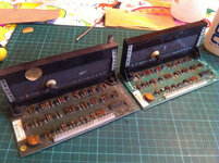
Paragon: Display Restoration by staticboy, on Flickr
The display on the left is very dusty and grimy, all sort of peeling labels and general black dust grot. The display on the right has had a good dusting, all the shabby labels picked off and old adhesive removed with alcohol. From the five displays this is all the rubbish that came off:
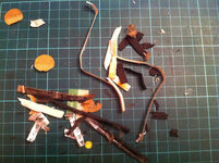
Paragon: Display Restoration by staticboy, on Flickr
Next I carefully removed the top half of the black plastic surround and cleaned it with Novus #1. I then worked on the lower half which had to remain in-situ on the PCB board. This type of plastic comes up really shiny! I also carefully cleaned the display glass with alcohol and then glass cleaner:
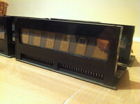
Paragon: Display Restoration by staticboy, on Flickr
I also use a little alcohol to clean the waxed-card high-voltage "safety" covers - remember these displays use 190V to fire up that plasma. It's gonna hurt if you touch 'em when they're turned on (and likely for quite a while after they've been turned off too, that a pretty big capacitor in the regulator board):
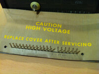
Paragon: Display Restoration by staticboy, on Flickr
All clean (must fashion a little rubber cover for that exposed nipple - ooh err):
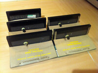
Paragon: Display Restoration by staticboy, on Flickr
You may have noticed in the above photo that one of the displays is different in that it doesn't have a sealing nipple on the back. Judging by the sticker this display was last serviced back in 1985:
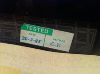
Paragon: Display Restoration by staticboy, on Flickr
A lot of the grot that I picked off was the remnants of foam strips that ran vertically up the sides of each display. Most probably this is to provide a cushion against the backglass but possibly also to prevent light bleed (but why not top and bottom too?). To replace this I ordered a small sheet of self-adhesive 2mm neoprene-type foam from a camera repair specialist on eBay. The foam is used as blackout lining in old cameras but is a perfect replacement the the displays. I simply cut 6mm wide strips using a new scalpel, each about 200 mm long and two per display:
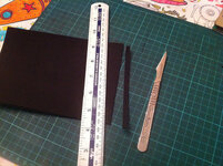
Paragon: Display Restoration by staticboy, on Flickr
In case you're wondering, I am working on a colour-it-in-yourself table cloth and drink my coffee out of a Moshi Monsters mug:
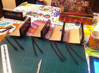
Paragon: Display Restoration by staticboy, on Flickr
Then it was a simple matter of removing the backing and carefully laying down in place. I started on the underside of the PCB just above the securing screw, working my up the edge:
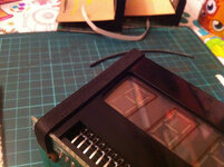
Paragon: Display Restoration by staticboy, on Flickr
And then over the top and down the rear thus securing the top of the black plastic case back in place:
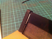
Paragon: Display Restoration by staticboy, on Flickr
So, all clean, shiny and new looking ready for refitting once the electrical improvements have been done. I'm beginning to think I might be over-doing things a bit - no one's going to see the ruddy things! But I'll know how peachy they are
DISPLAYS OVERHAUL
I've been very fortunate that all five 6-digit displays in my Paragon are fully working. Not bad for a bunch of 35-year old gas plasma displays! I will in due course be making the recommended upgrade of replacing the 100k ohm 1/4 Watt resistors R1, R3, R5, R7, R9 and R11 with modern 1/2 Watt equivalents with a slight stand-off to improve cooling. I'll also be re-flowing the solder on all joints and polishing the header pins - another hot topic of debate! Polish or replace? My pins still look pretty shiny and show little evidence of repeated connector cycling (Molex Trifurcons have a limited lifespan of connect/disconnect operations - I can't remember what the number is? 25-30 times?)
So here's a general before and after shot:

Paragon: Display Restoration by staticboy, on Flickr
The display on the left is very dusty and grimy, all sort of peeling labels and general black dust grot. The display on the right has had a good dusting, all the shabby labels picked off and old adhesive removed with alcohol. From the five displays this is all the rubbish that came off:

Paragon: Display Restoration by staticboy, on Flickr
Next I carefully removed the top half of the black plastic surround and cleaned it with Novus #1. I then worked on the lower half which had to remain in-situ on the PCB board. This type of plastic comes up really shiny! I also carefully cleaned the display glass with alcohol and then glass cleaner:

Paragon: Display Restoration by staticboy, on Flickr
I also use a little alcohol to clean the waxed-card high-voltage "safety" covers - remember these displays use 190V to fire up that plasma. It's gonna hurt if you touch 'em when they're turned on (and likely for quite a while after they've been turned off too, that a pretty big capacitor in the regulator board):

Paragon: Display Restoration by staticboy, on Flickr
All clean (must fashion a little rubber cover for that exposed nipple - ooh err):

Paragon: Display Restoration by staticboy, on Flickr
You may have noticed in the above photo that one of the displays is different in that it doesn't have a sealing nipple on the back. Judging by the sticker this display was last serviced back in 1985:

Paragon: Display Restoration by staticboy, on Flickr
A lot of the grot that I picked off was the remnants of foam strips that ran vertically up the sides of each display. Most probably this is to provide a cushion against the backglass but possibly also to prevent light bleed (but why not top and bottom too?). To replace this I ordered a small sheet of self-adhesive 2mm neoprene-type foam from a camera repair specialist on eBay. The foam is used as blackout lining in old cameras but is a perfect replacement the the displays. I simply cut 6mm wide strips using a new scalpel, each about 200 mm long and two per display:

Paragon: Display Restoration by staticboy, on Flickr
In case you're wondering, I am working on a colour-it-in-yourself table cloth and drink my coffee out of a Moshi Monsters mug:

Paragon: Display Restoration by staticboy, on Flickr
Then it was a simple matter of removing the backing and carefully laying down in place. I started on the underside of the PCB just above the securing screw, working my up the edge:

Paragon: Display Restoration by staticboy, on Flickr
And then over the top and down the rear thus securing the top of the black plastic case back in place:

Paragon: Display Restoration by staticboy, on Flickr
So, all clean, shiny and new looking ready for refitting once the electrical improvements have been done. I'm beginning to think I might be over-doing things a bit - no one's going to see the ruddy things! But I'll know how peachy they are
Last edited:
Fantastic stuff. Really appreciate the level of detail that you're documenting.
I'm beginning to think I might be over-doing things a bit - no one's going to see the ruddy things! But I'll know how peachy they are
Not in the slightest, those cushions are indeed most likely protecting the backglass from possible rubbing of the displays, so very important!
"I also use a little alcohol to clean the waxed-card high-voltage "safety" covers - remember these displays use 190V to fire up that plasma. It's gonna hurt if you touch 'em when they're turned on (and likely for quite a while after they've been turned off too, that a pretty big capacitor in the regulator board):"
Bally (and Stern, who copied the hardware), included a resistor in the 190v reg. circuit to bleed away the remaining charge when the power is off. According to a book about the early systems, it should be safe after about 60 seconds.
Last edited:
Bally (and Stern, who copied the hardware), included a resistor in the 190v reg. circuit to bleed away the remaining charge when the power is off. According to a book about the early systems, it should be safe after about 30 seconds.
Interesting! Maybe that'd be R35, a 100K 1W resistor wired across C26? If so, by my calculations, assuming an initial voltage of 230V (from the CR1-4 bridge on the transformer module) the cap would still have about 35V on it after 30 seconds. You'd need about 90 seconds for it to drop right down to less than 1 volt. 35V is probably quite safe but I've had zap from an old CRT TV long after it was unplugged so I always leave a wide margin of safety!
I'm very interested to know which book is you're referencing? Would be great to get a copy.
Peter,
It's a soft-bound book titled 'Electronic Pinball Electronics for Pinball Mechanics', Part 2, by author 'Hornick'. I did have Part 1 as well, which covered basic electronic principles, but that's gone missing. Part 2 covers the early Bally, Williams and Gottlieb sysytems. I'm not likely to need it now, so let me know if it'd help you out.
It's a soft-bound book titled 'Electronic Pinball Electronics for Pinball Mechanics', Part 2, by author 'Hornick'. I did have Part 1 as well, which covered basic electronic principles, but that's gone missing. Part 2 covers the early Bally, Williams and Gottlieb sysytems. I'm not likely to need it now, so let me know if it'd help you out.
Last edited:
F
Friz
Thoroughly enjoying this thread. great work!
January 2014
FLIPPERS
After a thoroughly wet and miserable winter I have finally emerged from my hibernation and ventured back out to the summerhouse/home-office. Time to dust off my tools and get restoring again. The backbox is still in progress along several lines. The displays are done as are most of the lamp holders. I removed the earth braid, circuit board brackets, various fixings and carefully un-stapled the foil shield. I'll do a separate write-up on the details as things start to come together.
But to really get back into the swing of things I decided to "treat" myself to some real pinball renovation: FLIPPERS.
I started by removing the lower right-hand flipper from the underside of the playfield. First I took several reference photos of the wiring and then unsoldered the coil connections. Next an Allen key was required to undo the 2 grub screws (Set Screw M-1369) that lock the flipper shaft into the lever arm (A-3711-3). Pull the flipper out from the topside, then undo four retaining screws that hold the entire assembly A-1587-102 to the playfield:
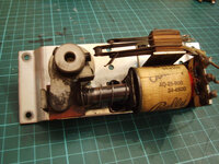
Paragon: Flipper rebuild by staticboy, on Flickr
And the underside. Yuck!
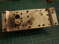
Paragon: Flipper rebuild by staticboy, on Flickr
Undo the two screws holding the coil bracket (P-108-53) and slide out the plunger & link assembly (A-3714-1). Note the coil he has slipped sideways because there was only one lose screw holding in the coil stop!
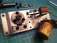
Paragon: Flipper rebuild by staticboy, on Flickr
Coil (AQ-25-500 34-4500) looks good!
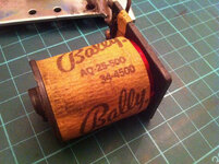
Paragon: Flipper rebuild by staticboy, on Flickr
End of the plunger and coil stop could be better but not particularly mushroomed. I'll see how they go for now.
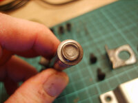
Paragon: Flipper rebuild by staticboy, on Flickr
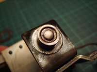
Paragon: Flipper rebuild by staticboy, on Flickr
Bearing (C-649-53) wasn't cracked but seen better days, and I'd already picked up some new ones at UK Pinball Party 2013:
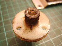
Paragon: Flipper rebuild by staticboy, on Flickr
Double switch assembly prior to removal (Paragon has double flippers so extra NO EOS switch to activate upper flipper):
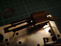
Paragon: Flipper rebuild by staticboy, on Flickr
Flipper stop (P-6665-444):
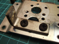
Paragon: Flipper rebuild by staticboy, on Flickr
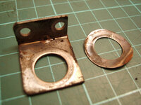
Coil bracket (P-108-53) and spring washer (P-1158-6):
Paragon: Flipper rebuild by staticboy, on Flickr
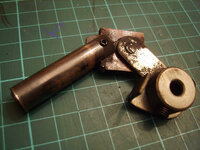
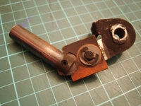
Complete plunger & link assembly (A-3714-1):
Paragon: Flipper rebuild by staticboy, on Flickr
Paragon: Flipper rebuild by staticboy, on Flickr
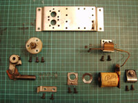
All the original parts laid out roughly in the position they fit to the bracket:
Paragon: Flipper rebuild by staticboy, on Flickr
Mounting bracket top and bottom (P-6264-134):
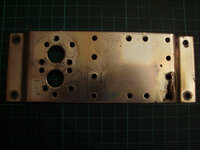
Paragon: Flipper rebuild by staticboy, on Flickr
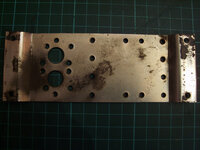
Paragon: Flipper rebuild by staticboy, on Flickr
Mounting bracket after a little Autosol:

Paragon: Flipper rebuild by staticboy, on Flickr
And then after a little work with my metal polishing kit (a kit of 3 wheels/mops that fit onto a standard electric drill):
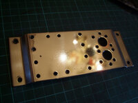
Paragon: Flipper rebuild by staticboy, on Flickr
Next I moved on to the leaf switches. Here are the parts "exploded" in assembly order for ASW-A10-45 (the NO part of the EOS):
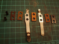
Paragon: Flipper rebuild by staticboy, on Flickr
And then after a little TLC with some Autosol and sandpaper:
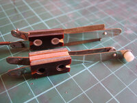
Paragon: Flipper rebuild by staticboy, on Flickr
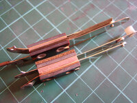
Paragon: Flipper rebuild by staticboy, on Flickr
At this point I started putting the flipper assembly back together by mounting the brand new bearing (C-649-53) with screws (SFPP-00832-1106) that I buffed to mirror finish. Also polished and refitted is the switch bracket P-126-718:
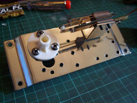
Paragon: Flipper rebuild by staticboy, on Flickr
That's all I got for now. I did take the buffing wheel to everything else but haven't taken any photos yet. More to come in FLIPPERS PT.2!
FLIPPERS
After a thoroughly wet and miserable winter I have finally emerged from my hibernation and ventured back out to the summerhouse/home-office. Time to dust off my tools and get restoring again. The backbox is still in progress along several lines. The displays are done as are most of the lamp holders. I removed the earth braid, circuit board brackets, various fixings and carefully un-stapled the foil shield. I'll do a separate write-up on the details as things start to come together.
But to really get back into the swing of things I decided to "treat" myself to some real pinball renovation: FLIPPERS.
I started by removing the lower right-hand flipper from the underside of the playfield. First I took several reference photos of the wiring and then unsoldered the coil connections. Next an Allen key was required to undo the 2 grub screws (Set Screw M-1369) that lock the flipper shaft into the lever arm (A-3711-3). Pull the flipper out from the topside, then undo four retaining screws that hold the entire assembly A-1587-102 to the playfield:

Paragon: Flipper rebuild by staticboy, on Flickr
And the underside. Yuck!

Paragon: Flipper rebuild by staticboy, on Flickr
Undo the two screws holding the coil bracket (P-108-53) and slide out the plunger & link assembly (A-3714-1). Note the coil he has slipped sideways because there was only one lose screw holding in the coil stop!

Paragon: Flipper rebuild by staticboy, on Flickr
Coil (AQ-25-500 34-4500) looks good!

Paragon: Flipper rebuild by staticboy, on Flickr
End of the plunger and coil stop could be better but not particularly mushroomed. I'll see how they go for now.

Paragon: Flipper rebuild by staticboy, on Flickr

Paragon: Flipper rebuild by staticboy, on Flickr
Bearing (C-649-53) wasn't cracked but seen better days, and I'd already picked up some new ones at UK Pinball Party 2013:

Paragon: Flipper rebuild by staticboy, on Flickr
Double switch assembly prior to removal (Paragon has double flippers so extra NO EOS switch to activate upper flipper):

Paragon: Flipper rebuild by staticboy, on Flickr
Flipper stop (P-6665-444):

Paragon: Flipper rebuild by staticboy, on Flickr
Coil bracket (P-108-53) and spring washer (P-1158-6):

Paragon: Flipper rebuild by staticboy, on Flickr
Complete plunger & link assembly (A-3714-1):

Paragon: Flipper rebuild by staticboy, on Flickr

Paragon: Flipper rebuild by staticboy, on Flickr
All the original parts laid out roughly in the position they fit to the bracket:

Paragon: Flipper rebuild by staticboy, on Flickr
Mounting bracket top and bottom (P-6264-134):

Paragon: Flipper rebuild by staticboy, on Flickr

Paragon: Flipper rebuild by staticboy, on Flickr
Mounting bracket after a little Autosol:

Paragon: Flipper rebuild by staticboy, on Flickr
And then after a little work with my metal polishing kit (a kit of 3 wheels/mops that fit onto a standard electric drill):

Paragon: Flipper rebuild by staticboy, on Flickr
Next I moved on to the leaf switches. Here are the parts "exploded" in assembly order for ASW-A10-45 (the NO part of the EOS):

Paragon: Flipper rebuild by staticboy, on Flickr
And then after a little TLC with some Autosol and sandpaper:

Paragon: Flipper rebuild by staticboy, on Flickr

Paragon: Flipper rebuild by staticboy, on Flickr
At this point I started putting the flipper assembly back together by mounting the brand new bearing (C-649-53) with screws (SFPP-00832-1106) that I buffed to mirror finish. Also polished and refitted is the switch bracket P-126-718:

Paragon: Flipper rebuild by staticboy, on Flickr
That's all I got for now. I did take the buffing wheel to everything else but haven't taken any photos yet. More to come in FLIPPERS PT.2!
Amazing what a bit of elbow grease can do.
Lookin good.
Lookin good.
February 2014
A8 SOUND MODULE UPGRADE
I hope this isn't going to be a case of "Don't fix what ain't broke" but using the parts listed in Big Daddy's Bally AS-2518-50 Sound Module Capacitor Kit as a guide I've done a little maintenance and upgrading on the sound board. The sound always worked after I got Paragon working again but very occasionally it would fire a "squeaky fart" instead of convincing ping, so maybe it's got a duff component. Electrolytic capacitors are known for not lasting forever (especially those made 35 + years ago) and are cheap (the 6 I replaced cost £2.51).
First up was to reflow the solder on the pins of the Molex connectors J1 and J2. I should have taken a "before" photo as there were tell-tale signs of dry joints on pin 1 to 3 (hairline dark ring where solder meets board):
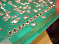
Paragon: Sound Module Upgrade by staticboy, on Flickr
The following electrolytic capacitors were then replaced being careful to get the (+/-) polarity correct!
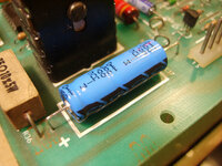
Paragon: Sound Module Upgrade by staticboy, on Flickr
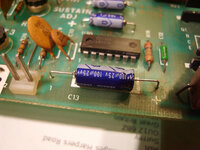
Paragon: Sound Module Upgrade by staticboy, on Flickr
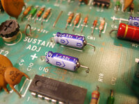
Paragon: Sound Module Upgrade by staticboy, on Flickr
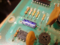
Paragon: Sound Module Upgrade by staticboy, on Flickr
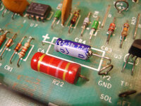
Paragon: Sound Module Upgrade by staticboy, on Flickr
On the underside of the board two of the mounting holes have exposed plated areas that make electrical contact with the mounting brackets and therefore with the grounding plane. It makes sense to give these a thorough clean, here using my trusty "fibreglass pencil" - like this from Maplin but you can get them cheaper elsewhere. I also used it to polish the connector pins, which are in perfectly serviceable order.
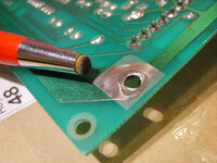
Paragon: Sound Module Upgrade by staticboy, on Flickr
I've labelled the board and connectors using my trusty Dymo LetraTag 2000, then back in it's little box for the time being:
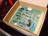
Paragon: Sound Module Upgrade by staticboy, on Flickr
A8 SOUND MODULE UPGRADE
I hope this isn't going to be a case of "Don't fix what ain't broke" but using the parts listed in Big Daddy's Bally AS-2518-50 Sound Module Capacitor Kit as a guide I've done a little maintenance and upgrading on the sound board. The sound always worked after I got Paragon working again but very occasionally it would fire a "squeaky fart" instead of convincing ping, so maybe it's got a duff component. Electrolytic capacitors are known for not lasting forever (especially those made 35 + years ago) and are cheap (the 6 I replaced cost £2.51).
First up was to reflow the solder on the pins of the Molex connectors J1 and J2. I should have taken a "before" photo as there were tell-tale signs of dry joints on pin 1 to 3 (hairline dark ring where solder meets board):

Paragon: Sound Module Upgrade by staticboy, on Flickr
The following electrolytic capacitors were then replaced being careful to get the (+/-) polarity correct!
- C17 100uF 100V
- C13 100uF 25V
- C8, C11, C23 1uF 50V
- C6 2.2uF 50V

Paragon: Sound Module Upgrade by staticboy, on Flickr

Paragon: Sound Module Upgrade by staticboy, on Flickr

Paragon: Sound Module Upgrade by staticboy, on Flickr

Paragon: Sound Module Upgrade by staticboy, on Flickr

Paragon: Sound Module Upgrade by staticboy, on Flickr
On the underside of the board two of the mounting holes have exposed plated areas that make electrical contact with the mounting brackets and therefore with the grounding plane. It makes sense to give these a thorough clean, here using my trusty "fibreglass pencil" - like this from Maplin but you can get them cheaper elsewhere. I also used it to polish the connector pins, which are in perfectly serviceable order.

Paragon: Sound Module Upgrade by staticboy, on Flickr
I've labelled the board and connectors using my trusty Dymo LetraTag 2000, then back in it's little box for the time being:

Paragon: Sound Module Upgrade by staticboy, on Flickr
