What's new
Pinball info

Register a free account today to become a member! Once signed in, you'll be able to participate on this site by adding your own topics and posts, as well as connect with other members through your own private inbox!

In Progress Adventures in Budget Restoration: 1978 Bally PARAGON

Nedreud

Registered
Joined
Feb 12, 2013
Messages
3,092
Location
Aldershot, UK
I got my project 1978 Bally Paragon on Good Friday 2013 for the princely sum of £150. It was sold as seen and a known non-worker. But the very nice Dave2084 who helped with the sale does pin repair in his spare time and he checked over a few bits: the power supply was ok, as was the voltage regulator and displays. Just the MPU (motherboard) appeared to be lifeless but had the usual battery corrosion.

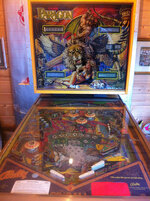
Here she is the day she arrived:

8616324352_46a71fab06_c.jpg

I've been tinkering ever since and have managed to rebuild the power supply and bring the MPU back from the dead! Now that I'm really getting stuck in I wanted to record my progress for posterity and hopefully help (and get help from) the pinball community. I'm not a rich man but I'm capable, persistent and a perfectionist, so there will probably be some very odd things happening with this pin. Could be worth watching... ;)

Fingers crossed I'll be able to do right by this pin and live up to its name.
 
Last edited:
Did you get some legs with it or just not got round to putting them on in that picture?
Yes, it came with a set of legs but no bolts. The photo was taken right after I got it home. Back-box was just resting on top too as no bolts for that either.
 
No backbox bolts.... now there's a surprise... :rolleyes:
There's a reason for that... this pin has a very sad story attached to it. It was going to be this guys next project pin. Dave2084 was his local pinball repair guy and buddy, and I think he'd helped pick it up originally. Then quite unexpectedly the owner passed away. I don't know the exact details, but I think he was only in his middle ages. His wife wanted to keep his other two working pins, but the Paragon was just folded up wasting space in the corner. When me and Dave2084 collected it we really had to hunt around to find the legs and backglass - his poor wife was still clearly in shock and looked so lost.

So this one's a keeper and I'm going to do my best to restore it to it's former glory. My goal is to have it done ready to take to the UK Pinball Party 2014 for all to enjoy. I'd love to take it to the school Christmas Fair to help raise funds but know that's overly optimistic this year, but hopefully it should be in good shape for next year's Summer Fair - 50p a game with prizes for the top scores - my way of bringing pinball to the kids and balancing karma.
 
I am aware of the circumstances of your aquisition and wasn't referring to that and yes it is a very sad story. :(

It was a comment on that almost every pin that has backbox bolts has them missing...! :)

Perhaps it was uncalled for in this instance given the circumstances. Sorry.
 
Perhaps it was uncalled for in this instance given the circumstances. Sorry.
Hey! No problem! :) I didn't take it that way. But you're right - it wasn't a surprise. Where do all these important little things get to? I recently learnt a new word that describes the battle between man (more accurately men) and inanimate objects:

Resistentialism
Resistentialism is a jocular theory to describe "seemingly spiteful behavior manifested by inanimate objects." For example, objects that cause problems (like lost keys or a runaway bouncy ball) exhibit a high degree of malice toward humans and lend support to resistentialist beliefs. In other words, a war is being fought between humans and inanimate objects, and all the little annoyances objects give people throughout the day are battles between the two.
 
Before

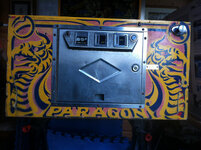
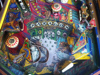
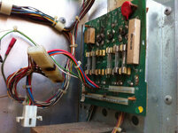
For reference, here are a few pics of what I started with back in May 2013:

farm9.staticflickr.com_8252_8616324440_107ec56c57_c.jpg
Paragon: overview by staticboy, on Flickr

farm9.staticflickr.com_8543_8616323944_8df8bb6d92_c.jpg
Paragon: cabinet front by staticboy, on Flickr

farm9.staticflickr.com_8385_8616322424_8afc84057f_c.jpg
Paragon: middle playfield by staticboy, on Flickr

farm9.staticflickr.com_8401_8669549540_227e89a05a_c.jpg
Paragon: Power supply board by staticboy, on Flickr

farm9.staticflickr.com_8389_8669545648_b632339be8_c.jpg
Paragon: MPU corrosion by staticboy, on Flickr
 
Last edited:
The next few post are going to be a bit of a retrospective from my point of view and will make it look like I'm working really fast.

April-May 2013
Rebuild and Upgrade AS-2518-18 RECTIFIER BOARD ASSEMBLY

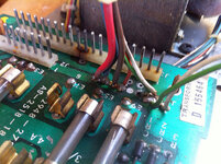
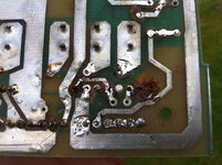
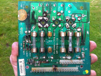
It all looked a bit dodgy to me; missing fuse, hard-wired connector hack, strange auxiliary power feed using automotive crimp connectors, burnt pins, singed components and general grot:

farm9.staticflickr.com_8403_8669550614_22ca3d569b_c.jpg
Bally Paragon: by staticboy, on Flickr

farm9.staticflickr.com_8404_8668452667_6f9840386a_c.jpg
Bally Paragon: by staticboy, on Flickr

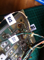
Stripped everything off except the fuse holders as I thought they didn't look too bad and would see how they cleaned up. Labelled each wire carefully as I removed it from the underside:

farm9.staticflickr.com_8392_8668471957_ea62074522_c.jpg
Bally Paragon: by staticboy, on Flickr

farm9.staticflickr.com_8386_8668473607_ffe53ef9c3_c.jpg
Bally Paragon: by staticboy, on Flickr

farm9.staticflickr.com_8396_8668475461_a16f16198f_c.jpg
Bally Paragon: by staticboy, on Flickr

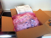
Large bag of replacement parts from MOUSER UK:

farm8.staticflickr.com_7304_8747658740_2633c571be_c.jpg
Paragon: Electronic goodies from Mouser by staticboy, on Flickr

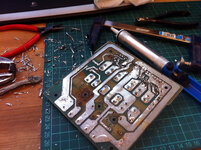
Pulling off components and removing as much old solder as possible with a manual pump:

farm8.staticflickr.com_7352_8751924384_0dd92360a4_c.jpg
Paragon: Rectifier clean-up by staticboy, on Flickr

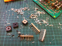
All the grot left over:

farm8.staticflickr.com_7374_8750803571_61be86a84a_c.jpg
Paragon: Old rectifier parts by staticboy, on Flickr

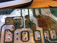
End result of removing all the components. Many of the stand-alone copper tracks lifted off the board, especially on the underside where the totally inadequate 8A bridge rectifiers were mounted:

farm6.staticflickr.com_5442_8750806655_608f77d9a8_c.jpg
Paragon: Rectifier board underside by staticboy, on Flickr

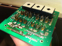
After a good clean-up with fibreglass pencil and some Dremel work with a brass brush on the fuse holders I started to test fit the new uprated 400V 35A bridge rectifiers. Due to their size these are now mounted on the top-side and will each get their own heatsinks:

farm6.staticflickr.com_5446_8750810283_fc121bbf28_c.jpg
Paragon: Test fitting rectifiers by staticboy, on Flickr

Improvements are repairs to the track-work both top and bottom. The upgrades help improve the conductive areas for the ground lines:

farm4.staticflickr.com_3768_8779540387_c52fe2f873_c.jpg
Paragon: PSU repairs and upgrades by staticboy, on Flickr

farm4.staticflickr.com_3669_8779538399_4950e689d7_c.jpg
Paragon: 0.156" header pins by staticboy, on Flickr

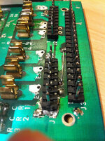
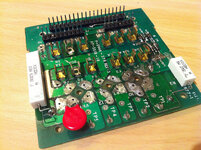
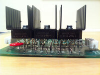
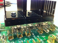
Re-fitting new components. Because of the new bridge rectifiers I "floated" the power resistors and kept them proud of the PCB surface to improve airflow and cooling:

farm9.staticflickr.com_8129_8779538853_71f19c6b11_c.jpg
Paragon: Rectifier board by staticboy, on Flickr

farm3.staticflickr.com_2833_8779536373_26a6747fb8_c.jpg
Paragon: Bridges + heatsinks by staticboy, on Flickr

farm4.staticflickr.com_3713_8779535595_36f8500787_c.jpg
Paragon: PSU Heatsinks by staticboy, on Flickr

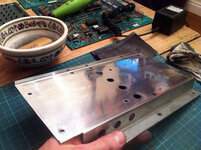
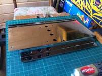
I then did a lot of work with increasing grades of wet'n'dry paper and AUTOSOL to polish the A2 POWER TRANSFORMER MODULE mounting plate:

farm8.staticflickr.com_7281_8739727108_2db02dceaf_c.jpg
Paragon: PSU bracket #7 by staticboy, on Flickr

farm4.staticflickr.com_3787_8902514706_071e821317_c.jpg
Paragon: Final polish on PSU by staticboy, on Flickr

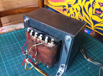
And I polished up the transformer and it's brackets too:

farm9.staticflickr.com_8394_8902513308_5974924c91_c.jpg
Paragon: Final polish on PSU by staticboy, on Flickr

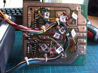
So glad I numbered those wires!!!

farm8.staticflickr.com_7330_8902508912_db56e64017_c.jpg
Paragon: Re-wiring the PSU by staticboy, on Flickr

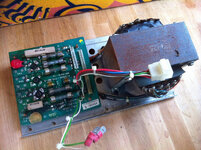
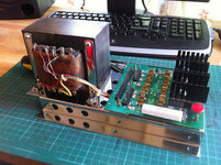
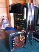
And this is the end result: one clean, shiny but most importantly sufficiently rated A2 POWER TRANSFORMER MODULE (which got rid of quite a lot of hum):

farm6.staticflickr.com_5468_8902506882_fd30d59101_c.jpg
Paragon: PSU Assembled by staticboy, on Flickr

farm9.staticflickr.com_8140_8901889605_a603fa8afb_c.jpg
Paragon: PSU finished by staticboy, on Flickr

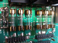
Time to put in all the correctly rated fuses:

farm8.staticflickr.com_7436_8901886471_ebdc6741cc_c.jpg
Paragon: New fuses by staticboy, on Flickr

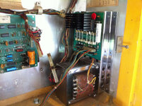
And put it back where it belongs. And yes, I did replace all the burnt Molex connectors!

farm8.staticflickr.com_7318_8901883125_f362a0a2ed_c.jpg
Paragon: PSU re-fitted into backbox by staticboy, on Flickr
 
Last edited:
I didn't see that thread, thanks, but I definitely watched that video on YouTube. Very information part of my research!

Great stuff. Thanks for posting. :cool:
Thank you :p Plenty more to come.

Next up... resurrecting the MPU/motherboard. Da-da-DAH!!! :eek: (Picture Frankenstein as he flicks the switch to re-animate his creation)
 
woah. i don't understand *any* of what i just read, but enjoyed it nonetheless. there were boards and fuses and wires and all sorts of stuff going on, i especially liked the pic of all the crap you pulled off the busted up board.
 
Great stuff. Thanks for posting. :cool:
My pleasure!
This is a proper 'Phoenix' project, keep it coming!
Phoenix. Yeah, I like that! Will do...
I love restoration threads with loads of photos. Great work :cool:
You want photos? I got lots of photos...

April-May 2013
Resurrect the AS-2518-35 MPU MODULE

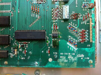
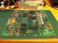
The one thing I knew for certain when I bought Paragon was that the MPU wasn't working. Dave2084 reassured me it was nearly always possible to fix these boards and that this one didn't look too bad. As I now know it's almost de facto in this era of machines for the MPU to suffer from battery corrosion damage. This one got away fairly lightly because I think the back-box had been stored on its side. The damage is along the bottom edge as usual but mostly to the right-hand corner and up the right-hand side. In the back-box the corrosion was on the right-hand mounting bracket and further over to the right towards the voltage regulator board.

farm9.staticflickr.com_8262_8673952601_b7cd9d8f95_c.jpg
Paragon: MPU A4 AS-2518-35 by staticboy, on Flickr

To make testing nice and easy I realised it would be best to get it out of the cabinet and onto the bench. To do this I needed a stand-alone power supply and I didn't really want to use the one out of the machine itself - too many high voltages, uncovered live wires, etc. Then I came across this site:

http://techniek.flipperwinkel.nl/

It's in Dutch (which you can translate in-line if you use the Google Chrome web browser) but if you dig around you'll find a truly awesome repository of information in English about fixing old Bally SS machines:

Repairing Bally Electronic Pinball Games from 1977 to 1985

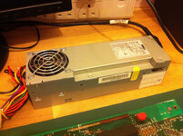
One nugget of info from there is to use an old ATX computer power supply to supply the +5V and +12V required to power the MPU. Computers are my living so I've got plenty of these lying around. This one was pulled from a slimline Dell desktop:

farm9.staticflickr.com_8254_8673951017_86eaa642ca_c.jpg
Paragon: Spare Dell ATX PSU by staticboy, on Flickr

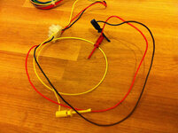
I then snipped off one of the floppy-drive power connectors and used a choccy block to connect three test leads with spring-loaded clips (Black = Ground, Red = +5V, Yellow = +12V):

farm9.staticflickr.com_8406_8673952725_69e33e4a64_c.jpg
Paragon: +5V, +12V and GND by staticboy, on Flickr

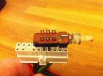
To switch an ATX PSU on you need to take Pin 14 (Green) low, i.e., to Ground. To make this easy I stuffed a long-tailed toggled switch between Pins 14 and 15. This is on the older 20-pin Molex connector. If you have a more recent 24-pin connector just bridge Pins 16 and 17. Pinout info on Wikipedia.

farm9.staticflickr.com_8526_8675055048_294d25f205_c.jpg
Paragon: On-Off Switch on Pins 14-15 of 20-pin ATX PSU by staticboy, on Flickr

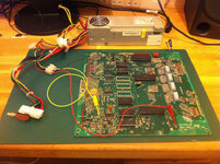
Test fixture ready to go... Black (Ground) clips onto TP4, Red (+5V) clips on TP5 and Yellow (+12V) clips onto TP2 (not TP3 right next to it which is part of the circuit to detect the +43V solenoid power):

farm9.staticflickr.com_8404_8673952623_0d12d7bd29_c.jpg
Paragon: MPU Test Setup by staticboy, on Flickr

Switch it on and... just a constant green light on the CR8 test LED:

farm9.staticflickr.com_8258_8675055496_b0562a910a_c.jpg
Paragon: Test LED by staticboy, on Flickr

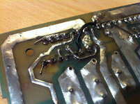
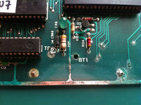
It was at this point I pulled all the chips from their sockets and reseated them. Still the same. So then I simply spent a long time using the digital multimeter to check the continuity between ground and anywhere I knew it should be by consulting the circuit diagram, e.g., Pin 1 of chips U10 and U11. Oh... BINGO! Dead track caused by corrosion right underneath where the battery was located:

farm9.staticflickr.com_8520_8675055526_bf1a8df902_c.jpg
Paragon: Broken Track by staticboy, on Flickr

Fixed this by bridging with some tinned copper wire and plenty of solder. Switched it back on and... WOOHOO! TWO FLASHES!!!

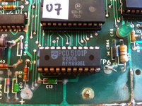
Two flashes tells you something is wrong with chip U8, the 5101 static RAM (used for storing game settings, high scores, etc.) I replaced with a new one from Pinball Mania and after a false start bending one of the pins and missing its socket I progressed to THREE FLASHES!!!


Here's the new chip (Philips PCD5101P) in a new turned-pin socket and you can see my repair to the ground line in the lower-right:

farm8.staticflickr.com_7285_8739717518_15130f46d2_c.jpg
Paragon: New U8 5101P by staticboy, on Flickr

The next two test flashes relate to chips U10 and U10 the 6820 PIA (Peripheral Interface Adapters). These guys allow the processor U9, a classic Motorola 6800 CPU, to communicate with the outside world (in the case of pinballs this means lamps, switches and solenoids). I tried swapping U10 and U11 over but no change so time for a pair of new chips. I got some 6821s - these are functional equivalents for the 6820 but have some extra TTL "stuff" that isn't used. Once fitted SIX FLASHES ahoy! Final seventh flash should show when the +43VDC for the solenoids is connected (this has to come from the main power supply in the pinball machine itself).


Of course, this meant that I was tantalisingly close to proving that I have fully working MPU! Temptation was too great. It simply had to go back in the machine:

FIRST SWITCH ON!

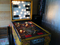
This is the first time I switched the machine on and let it run. I then opened the coin door and pressed the test button to first flash the switched illumination, then cycle the displays (not shown), then test the solenoids and finally run the sound. And it ALL WORKS! Well... got quite a few missing lamps and one of my pop bumbers has no ring...


Lots of lights!

farm4.staticflickr.com_3695_8901879177_ef3cb31559_c.jpg
Paragon: Playfield GI by staticboy, on Flickr

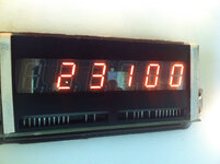
Which of course inevitably led to playing my first game and getting my first high score:

farm4.staticflickr.com_3797_8902485404_d94789ffe1_c.jpg
Paragon: MY FIRST HIGH SCORE! by staticboy, on Flickr

HAPPY DAYS! :D
 
Last edited:
woah. i don't understand *any* of what i just read, but enjoyed it nonetheless. there were boards and fuses and wires and all sorts of stuff going on, i especially liked the pic of all the crap you pulled off the busted up board.
My pleasure! As is your avatar to me ;)
 
I've moved the videos in my last post from Flickr to YouTube so that they can be embedded directly. Flickr rules for photos but YouTube is the king of video.
 
Last edited:
May 2013
Bits'n'Bobs

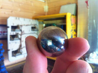
Along with the replacement 5101 chip I ordered some other bits. Most important of all, my first pinball:

farm8.staticflickr.com_7284_8738596879_395711b80e_c.jpg
Paragon: New pinball! by staticboy, on Flickr

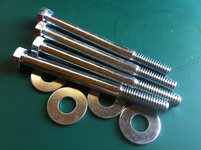
Along with new back-box bolts:

farm8.staticflickr.com_7287_8738596475_e407ffb436_c.jpg
Paragon: Backbox bolts by staticboy, on Flickr

And therein lies a tale...

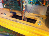
Whilst fitting the new bolts I found the rear-left one wouldn't tighten all the way down by about 2mm.

farm8.staticflickr.com_7288_8738597693_96e525082c_c.jpg
Paragon: Bolting on the backbox by staticboy, on Flickr

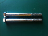
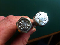
Turns out I had two pairs of different bolts:

farm8.staticflickr.com_7287_8739716988_225ed4fc09_c.jpg
Paragon: Mis-matched bolts by staticboy, on Flickr

The very slight difference in thread length and overall length meant that one type wouldn't quite tighten down when used in the rear holes.

farm8.staticflickr.com_7283_8739717252_1d2d209963_c.jpg
Paragon: Mis-matched bolts by staticboy, on Flickr

Both types are marked "307A" but there were two of each marked "HKT" and "CYI" which I guessed are manufacturer codes (both Chinese bolt makers as it turns out). One type had slightly longer threading (~2mm) and was about 1mm longer. Basically, the same bolt from different manufactures that are identical within fairly loose tolerances. Found out that the code 307A on a bolt head indicates that the fastener properties conform to the ASTM A307 Grade A Standard. Whatever. Just one of the many gotchas you'd never think of until it happens.
 
May 2013
Power Supply Safety Guard

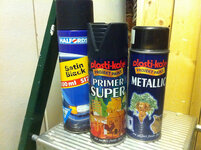
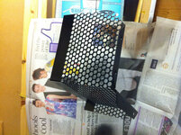
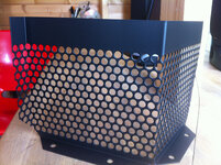
Inside the back-box there is a simple wire mesh that covers the high voltage terminals on the transformer to protect operators from accidental electrocution. As with most parts in this pin it had developed a fine surface rust. But nothing that 20 minutes with a 3" wire brush in a standard electric drill can't fix. After a good clean-up and rinse with isopropyl alcohol I primed with black plasti-kote SUPER PRIMER and then hit it with 3 or 4 very light coats of Halfords Satin Black:

farm8.staticflickr.com_7430_8884820232_19c02edf77_c.jpg
Paragon: Black spray paint by staticboy, on Flickr

farm4.staticflickr.com_3735_8884820134_4a6a5d7be0_c.jpg
image by staticboy, on Flickr

And I'm very pleased with the result!

farm9.staticflickr.com_8270_8893792128_f757f8ab8f_c.jpg
Paragon: Transformer safety guard by staticboy, on Flickr
 
Last edited:
That Plasti-kote comes out blooming lovely once you ave gotten used to spraying it :) Good job there :)
 
That Plasti-kote comes out blooming lovely once you ave gotten used to spraying it :) Good job there :)
Yes, I'm quite a fan of plasti-kote. It gets a bad rap I think because it's available in B&Q, etc. It does take a bit of getting used to, but so would anything. Always do some testing first. And spray in the right conditions. I'm no paint expert but spraying in a cold, clammy garage for instance is unlikely to produce good results. I always heat my little workshop to 25-30°C with fan heater. I do like the very slightly dimpled surface finish from the Halfords Satin Black though - almost looks like a powder coat.
 
June-September 2013
Research & Development: Playfield Restoration

My plan for the playfield doesn't involve a paint brush! :eek: Actually, I'm okay with a paint brush for detail work as I'm quite into Warhammer 40K and railway modelling. I can do airbrushing too, and I've read several blogs about restoring playfields using a "mask & spray" technique but almost without exception the playfields being restored have relatively simple geometric or straight-edged designs with block colours. There's an excellent guide to exactly this sort of restoration on pinside.com.

Vid's Guide to Ultimate Playfield Restoration
Vid1900 is very opinionated but seems to know what he's talking about. The topic starts up with info about replacing inserts, the details about airbrushing start about halfway down page 2. It's worth reading through at least once, it's stuffed full of good tips.
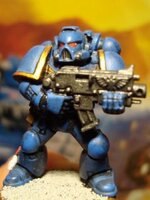
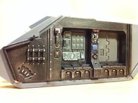
i590.photobucket.com_albums_ss344_peterduerden_WH40K.jpg i590.photobucket.com_albums_ss344_peterduerden_TANK.jpg

This simply isn't the case with Paragon which has some of the most detailed 10-colour screen-printed images to adorn a playfield (Paragon is probably most famous for it's beautiful artwork and many consider it one of the most beautiful pins ever made). Any attempt to hand re-paint it would be obvious. And I think that even with a water-slide decal of the top black screen layer it would still be too difficult to recreate the other 9 colours convincingly. The screen process creates a myriad of edge effects as the different colours overlap. My playfield simply has too much wear and the planking is so bad you can scratch the paint off down to bare wood with a finger nail. Where I gained on the underside (the hardware is in superb condition) I lost out on the topside. I can't complain - I got a working classic pinball machine for £150! Makes me smile every time I look at it :)

The chances of getting a NOS or A1 replacement are practically nil, and the last NOS that sold on eBay went for around $1,400 (nearly £900). That's probably double what I'm going to spend on this entire project! There is rumour that CPR (http://classicplayfields.com/) might be working on Paragon as they've done both plastics and backglass previously but again that's a lot of wonga and likely a very long wait.

So, the only other choice as I see it is an overlay. My take on it is that the original playfield is totally b*ggered and is beyond saving. If I use it as the base for an overlay and it works then at least it's mostly original. I can hear the cries of "Blasphemy!" already! But seriously, how else am I supposed to fix this:
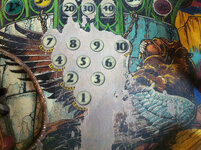
farm9.staticflickr.com_8262_8615217557_a6f5f27f16_c.jpg
Paragon: playfield centre - bonus score by staticboy, on Flickr

But how to make an overlay? It's just a giant sticker, right? I just need a image of the playfield and someone with a big printer. After some Googling and conversation on http://pinside.com/ I managed to obtain a hi-res scan of a NOS playfield:
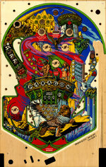
farm8.staticflickr.com_7327_8767554636_145db020e1_b.jpg
Super Hi-Res Scan of Paragon Playfield by staticboy, on Flickr

That's got to be the hard part, right? From this image the first thing I did was knock out the best print my £20 Canon inkjet printer could manage on standard copier paper, making sure it was scaled at exactly 100% without reducing resolution:
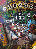
farm8.staticflickr.com_7348_9466951088_28ae02c3c4_c.jpg
Paragon: Test overlay by staticboy, on Flickr

Now come on! That's pretty impressive for a £20 printer from Asda! The scale is perfect. The aqua blue is spot on and the blacks dark. The yellow is a bit pale and the brown is way off, but not bad for a first test. Next, I tried the same experiment but this time using my Dad's colour laser printer on full glossy photo card stock. Unfortunately the stupid printer scaled the image to fit the A4 paper edge-to-edge so it's about 5% over-scaled:
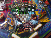
farm6.staticflickr.com_5326_9473729672_df620de4f7_b.jpg
Paragon: High quality test overlay by staticboy, on Flickr

Look at that! I can easily imagine that's the final finish, shiny clear coat and all:
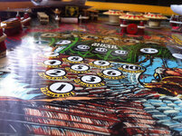
farm6.staticflickr.com_5548_9473728438_2b81ee5f4c_b.jpg
Paragon: High quality test overlay by staticboy, on Flickr

I have to admit I was seriously impressed with the print quality. Really crisp, no pixelation or dithering at all, and the colours are much better. With the two simple tests I decided it was time to go pro and order some test decals from an on-line service. I decided to try http://www.diginate.com/ first as you can order stickers/decals of any size or quantity, even singles.

First test, white vinyl with glossy (top) and matte (bottom) finish:
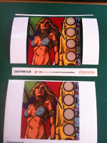
farm6.staticflickr.com_5341_9504291718_120ab778f3_b.jpgParagon: Test overlay vinyl stickers by staticboy, on Flickr

Admittedly, I wasn't too impressed with the result. There was even a little printer striping in the red. But I pressed on and experimented with clear-coating these samples to see how they would come out. Big improvement! Each sticker was also done with a different image. The top decal on glossy was done with a JPEG image and you can see in the image below there's slight dithering. The bottom decal on matte used a vectorised version of the image saved as a PNG. Vectorising the image attempts to turn areas into a solid block of a single colour thus minimising the dither of compressed image formats such as JPEG and keeping edges sharp. It also makes the images totally scalable without loss of resolution. I won't go into the technical details of vector images - I'm you're all half asleep at this point already.
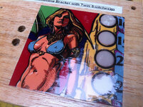
farm4.staticflickr.com_3704_9501578165_740a1c8f78_c.jpgParagon: Clear coat testing by staticboy, on Flickr

The colours look better and the gloss from the clear-coat! Ooh! Next test: clear vinyl. I realised that one disadvantage of using white vinyl is that although it's a good base to get vivid rich colours I'd have to cut holes for the inserts, re-level the inserts and re-decal the insert lettering. With clear vinyl there's no need to do any of this. Diginate.com allow you provide a masking layer in your artwork to control where they first print a white layer before applying any colour.

And here it is:
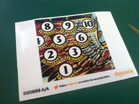
farm4.staticflickr.com_3827_10479115476_0f02b59d46_c.jpg
Paragon: Clear vinyl overlay test by staticboy, on Flickr

The colour is even better than the white vinyl and the transparent areas for the inserts have come out really well. Annoyingly I don't seem to have taken a photo of this decal in situ on the playfield, but it did look really good. The colours are a near perfect match even though they'd been reduced from RGB to CMYK (another technical detail concerning print reproductions). I recently stuck it on an off-cut of white Conti board and gave it a few coats of clear. It does look good! Will try to get a photo tomorrow in daylight.

So that's my plan. Get a ruddy huge clear vinyl sticker made to completely overlay the entire playfield in a single piece and then get it clear-coated (possibly professionally). Final cost of the decal from diginate.com will be around £50 delivered.
 
Last edited:
Seriously awesome work mate. It'll look great and £50 is a bargain when you consider how much a pf overlay normally costs.
I'm loving this thread. Can't wait to see the final result.
 
Back
Top Bottom