What's new
Pinball info

Register a free account today to become a member! Once signed in, you'll be able to participate on this site by adding your own topics and posts, as well as connect with other members through your own private inbox!

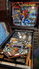
In Progress VIVA lost VECTOR

Another glimmer of hope on the horizon is that your SQUAWK & TALK is nearly done. I've been replacing the caps. Slow going as I'm taking the cautious approach by replacing them one at a time then re-testing. Also it's takes longer it has the advantage that I can tell straight away which cap isn't suitable if it happens to stop working, and will also be able to see where the biggest improvement to the audio quality occurs, e.g., reduced hiss, etc. I suspect that probably the new TDA2003 amplifier will be the biggest improvement.

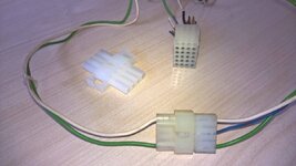
I'm sure I'll be dubbed the Antichrist but I still think soldering Molex pins is the best way to go. Saves the bother of buying a really expensive crimp tool too.

I've just been so busy with everything else except pinball recently that I've hardly had time to even look or post on here let alone play or restore my machines. But tonight I've promised both VECTOR and GOLD BALL to the school Christmas Fair so I have to pull my finger out and get them both working and shifted this afternoon! :eek:
 
I'm sure I'll be dubbed the Antichrist but I still think soldering Molex pins is the best way to go. Saves the bother of buying a really expensive crimp tool too.

Really, only solder to connect the Molex terminals? I'd assumed it was still crimp first and then solder using the £20 odd ratchet crimp tool that the guys on here recommend.

The good news is that I'm nearing the end of the wiring jigsaw - re-using and moving connectors about I'm just a couple of connector housings short per my Wanted post. Hence, I'm going to have to tool up to fit the Molex terminals having never done this before crimping, soldering or both. With the extra playfield loom from jaywalker I have loads of spare wire so can even mod using the correct colours.
 
I'm sure crimping is just fine but...

Pinball machines are not vibration free environments, to say the least. That's why I like to solder the wire into the body of the pins and then use some micro crimps to pinch the outer tangs into the cable casing. Best of both.

Whatever you it's going to be whole lot better that what you started with!!!
 
Thank you @Moonraker for the cash boxes and a great Friday evening at SWL. Really enjoyed MM and playing HS2 for my first time.

WP_20151208_14_38_22_Pro.jpg

Thank you @Jay Walker for yet more bits I need to make up the looms

WP_20151208_12_39_01_Pro.jpg
 
young neds pin certainly gets about:)
I've certainly honed my loading technique, that's for sure!

I want to finish off decorating the inside of my summer house. Want to fit a false flat ceiling to reduce the volume to keep it warmer (it's got quite a high vaulted ceiling so all the heat goes up there) and panel the falls, fit floor, secondary glazing, etc., but it's just not happening because I can't move for bloody pinball machines!

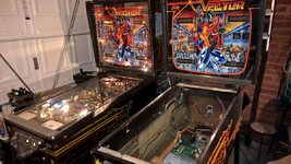
I thought by lending VECTOR to @astyy it'd kill two birds with one stone. Namely I'd free up some space and he'd have a working VECTOR for reference and testing.

I'm going to find a temporary home for GOLD BALL too so I won't have any playable pinball machines :( but that's also part of my plan... it'll give me the perfect incentive (and space) to finally finish my first love, PARAGON :)

It would of course help @astyy more if I'd remembered to take the bloody keys for VECTOR :mad: Muppet.
 
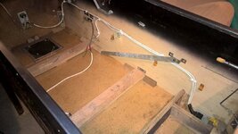
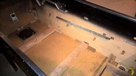
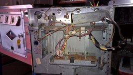
Finally stripped the cabinet of the alien white 3-core cabling.
WP_20151213_13_12_18_Pro.jpgWP_20151213_14_13_16_Pro.jpg

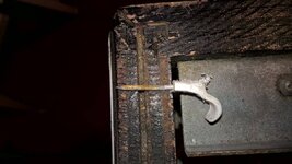
The cable clips were a git to remove and nearly long enough to poke through the outside of the cabinet!
WP_20151213_13_46_13_Pro.jpg

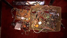
Then untangle my box of spaghetti.
WP_20151213_13_10_35_Pro.jpg

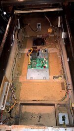
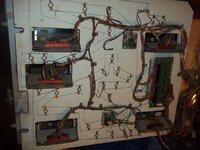
Here's the new cabinet loom installed complete with a new power cord and plug. I decided to route the new mains cable through the bracket at the back which has a decent cable grip. Other than that everything is back to standard with line filter, varistor, tilt mech board, flipper switches, knocker all in place.
WP_20160101_17_32_17_Pro.jpg

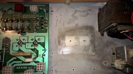
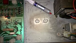
All voltages tested good from the transformer and then from the rectifier TPs. Time to heat seal the Rectifiers to the mounting plate using the 'peek through the holes' on the PCB method to align.
WP_20160101_16_13_00_Pro.jpg WP_20160101_16_14_41_Pro.jpg

Also I now have the reference VECTOR keys so working and setup. So far most research has been spent putting a few games on it :)
WP_20160101_17_32_56_Pro.jpg

This feels like progress the machine has been switched on for the first time and has 1 mech working a nice noisy Knocker!
 
Investigated the inside of the coin door today to check for shorts and tidied up the wiring also soldered on a missing coin slot GI. All of the coin mechs are missing as is the Volume pot other switches present.

Before & after
WP_20151027_12_43_04_Pro.jpg WP_20160109_16_20_18_Pro.jpg

Took the opportunity to insert the coin slot inserts that @Jay Walker provided me.
WP_20151128_07_07_47_Pro.jpg WP_20160109_16_20_32_Pro.jpg

Coin slots now lit - this machine is ready to go on site obviously ;)
WP_20160109_16_21_00_Pro__highres.jpg

A small victory but nice to have another thing working :)
 
Excellent stuff Aston. Edit - nice to see your progress with it.

Whilst @lukewells now has mine, it's staying here for at least a while and looking forward to setting it up and delving in with Luke to bring it back to life. :)
 
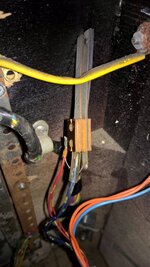
Nice little tidy up job today with the Elektra cab wiring loom I've installed in my VECTOR. Elektra has an extra feature switch on the left hand flipper not implemented on VECTOR but the switch matrix position is used on the upper play-field for the saucer kick-out. As this is a high end restore (;)) I wanted to isolate/remove it properly. The switch is daisy chained (two wires each side) on the strobe/return lines hence I couldn't just cut it back to the previous junction however the leads end on the coin door connector and I had enough cable to disconnect the live end from the switch pull back through the loom and connect straight to the coin door plug using my new Molex tool and replacing the female terminal pin.

Here's the alien switch removed from the flipper stack, note two wires to each terminal;

WP_20160116_13_28_59_Pro.jpg

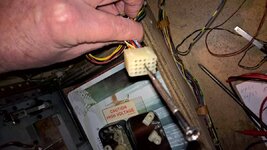
I pulled the wires out of the loom and removed the female pins from the coin door plug. Molex Female pins are tricky to remove (without the right tool) but can be done using a jewelers screwdriver by flattening the tangs at each side of the terminal and wiggling it out. The Male pins are easy to remove as the retaining tangs are accessible.

WP_20160116_14_11_45_Pro.jpg

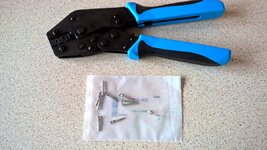
New Molex tool and female crimp terminals ready for action

WP_20160116_14_17_47_Pro.jpg

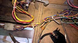
Re-routed wires tied in and job done .

WP_20160116_14_40_04_Pro.jpg

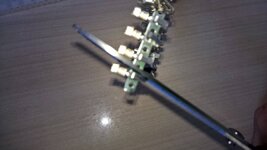
On the subject of Molex terminals I bought my mistake the strip ones not recommended in the Pin repair guides, however with a pair of office scissors and the right technique I found them easy to separate.

WP_20160116_10_30_26_Pro.jpg

My question on the Molex crimps is I found it hard to judge how far to push the wire into the crimp tool whilst it's holding the terminal ie to line up the insulation and bare wires properly. I was thinking maybe better to lightly crimp the terminal on to the wire and then insert into the tool?
 
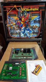
Has this really been sitting for 3 years :oops: - well progress of sorts to report, working boards and a shooter gauge cover acquired, many thanks to member @Dave2084 :thumbs:

88631

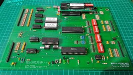
Oooh shiny new shiny board :cool: note extra one of Daves multigame PCBs onboard
88632

That's it for now, next update scheduled for 2022 :rofl:
 
What replacement board is that, not seen it before?
 
What replacement board is that, not seen it before?
I don't know much about it, something new(ish) that @Dave2084 is working on, he said it was ok to post pics so perhaps he'll comment.
 
What replacement board is that, not seen it before?

I won't take credit for the board it isn't my work, but I have been building and testing the prototypes and sending feedback.

This particular one is of course fully functional, still a few improvements before the design is final. The main issue with this revision is that the mounting holes on the right were slight out of position, I also asked for the DIP SW/Crystal area to be improved. (and why can't you get a 2Mhz Crystal in the HC49S form factor!)
 
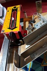
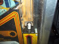
Reunited Vector with a shooter gauge today. There were a couple of supports left behind and I borrowed a third from the pf. I didn't realise it sat so high - is this right :hmm:
89016

One more piece of the jigsaw in place :D

89017
 
Flippin heck thought this might have been finished by now, it's been four years. Obviously you are in no rush to get it done, awaiting the next instalment.
 
A very "strange" game. I never did understand or get the hang of it!
Vector must be the marmite pin on here, it's surely complicated if TNT takes 15 minutes to explain the rules back in his 1980s vid (now on youtube). It's the detail of the lighting effects that I particularly like.

photo for reference,as promised
Thanks Steve, so as it "floats" the one you kindly offered with the missing prong would have worked after all :rolleyes:
 
Still on wiring ( :rolleyes: ) but been making some good progress over the last few days and my Vector Mojo is coming back👍. I'll write up some progress but have a few questions that perhaps fellow Vector owners could help with.

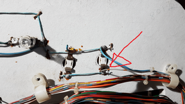
For starters an easy one. This loose blue wire on the loom to the Aux board - I think it goes where marked. The end at that point has been cut off and doesn't match the solder blob so I'm thinking this loom is "alien" too.

1563984274559.png

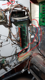
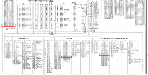
Next up more tricky, in same area, these are the Hi-Score lamps driven by the Grey/Brown (96) wire arrowed. According to the schematic this connects through A1J2-23 (the 24 pin back cab plug) to A4 J4-16 then to A3 J3-14. Pin 23 on the back cab plug isn't populated on my donor EBD loom so I must add it. I have pinned the correct connection between the MPU A4 and HV A3.

I'd really appreciate it if somebody could check that lamp socket, A4 J4-16 and A3 J3-14 are common and what would be really good is to find out where they are daisy chained - perhaps at A4 J4-16 as that is physically closest to the back box plug.

1563984871590.png


1563985006748.png

Finally, I have a kn*cked A3 J3 needing a 25-way 0.1" pitch molex - does anybody know a source please? Else, I'll get gluing a couple of smaller ones!

Thanks all.
 
Last edited:
Back
Top Bottom