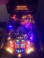
Small fry in the grand scheme of the work you guys have been doing, but finally got around to rebuilding my TZ clock. There wasn't really anything wrong with it, save for the fact that it was still using the OEM board with incandescents, when everything else in the game was LED. I'd bought an Ingo board, clear clock housing, gears, etc and felt like it was a mini project I could get my teeth into...
Getting the clock off of the playfield was more complicated than I thought it would be, mainly due to the piano mod obscuring screws. Wasn't sure how to remove it until a bright spark on Pinside coincidentally posted about removing one screw to rotate the clock out of position to gain access to the screws...

None of the guides I'd read mentioned that you had to remove the plastic over the piano slot in order to get the wires out...


With the clock finally removed from the playfield completely, I could strip it down without risk of losing the various E-rings, etc...

Everything disassembled slowly and methodically, and I took photos of how it was already assembled for my own peace of mind... The OEM board was surprisingly uncharred considering the horror stories I'd heard about the clock. The previous owner had drilled two holes into the casing which probably helped there.

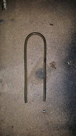
It was during disassembly that I discovered that the previous owner (or someone) had glued the non-moving shafts into the rear housing. This meant I couldn't use the new one I had bought to replace it, but fortunately it was in good shape anyway, and the replacement one I had was also cloudy rather than clear - so no real loss.
I followed the instructions for inserting the gears, adding a tiny bit of Teflon grease to the gear matings. One of the gears has a shorter tooth which has to line up with the opposite shaft...

The final white gear has two shorter teeth that are quite difficult to see with the naked eye. The easiest way to locate it is by looking at the line on the gear itself (see solid red arrow pointing to it). This gear has to be fitted on the shaft with the either of the two shorter teeth pointing at the one shorter tooth on the other gear above.

Sadly I didn't get a photo of fitting the big black gear, suffice to say that, like the final white gear, there is a black moulding line on both sides which you need to bisect the shaft you just fitted the white gear to.
If you've done all of this right, the clock will be bang on 12 o'clock when you power on the game. I managed to get it right first time by taking my time and following the somewhat inscrutable instructions ("Insert stub end of shaft into center hole of back panel, while aligning either of the two opposite, shorter teeth on smaller diameter gear of 03-8823 with remaining shaft", for example).
Unfortunately for me, after I put the clock back on the playfield and connected everything up the first time I switched it on - aside from being louder than I hoped it would be - it made a god awful clicking sound as the minute hand got caught on various opto holes. It turned out that because I installed a PETG prototype clock plate rather than a decal I had inadvertently removed any tolerance on the minute hand opto interrupter, and it was now fouling the plastic when it moved. This was further compounded by the fact that the minute hand drive pin was slightly bent when I disassembled the clock, so the hand didn't rotate consistently (clearing some optos, fouling others).

So... clock came off the machine again (strictly speaking I could've done this while it was installed, but I didn't know for sure what was wrong until I removed it and took a closer look). Following some advice I sanded down the minute hand opto interrupter, and reinstalled the clock - and now it works!


Although the saga hasn't really ended there because as it turns out I think I sanded off too much off the opto interrupter. The clock registers the time correctly, but the 30 minute opto doesn't register on the DMD consistently. Oddly in clock test it registers every opto perfectly, and the LEDs on the clock board confirm this.
The clock is also louder than I had expected it to be given that I used lube. I didn't oil the shafts which I've seen one guide recommend to do. I have ordered new minute hands & drive pins to have another go at it.
Anyway, sorry for so many images but thought it might help any similarly DIY challenged folk to disassemble the clock with more greater confidence.
Getting the clock off of the playfield was more complicated than I thought it would be, mainly due to the piano mod obscuring screws. Wasn't sure how to remove it until a bright spark on Pinside coincidentally posted about removing one screw to rotate the clock out of position to gain access to the screws...
None of the guides I'd read mentioned that you had to remove the plastic over the piano slot in order to get the wires out...
With the clock finally removed from the playfield completely, I could strip it down without risk of losing the various E-rings, etc...
Everything disassembled slowly and methodically, and I took photos of how it was already assembled for my own peace of mind... The OEM board was surprisingly uncharred considering the horror stories I'd heard about the clock. The previous owner had drilled two holes into the casing which probably helped there.
It was during disassembly that I discovered that the previous owner (or someone) had glued the non-moving shafts into the rear housing. This meant I couldn't use the new one I had bought to replace it, but fortunately it was in good shape anyway, and the replacement one I had was also cloudy rather than clear - so no real loss.
I followed the instructions for inserting the gears, adding a tiny bit of Teflon grease to the gear matings. One of the gears has a shorter tooth which has to line up with the opposite shaft...
The final white gear has two shorter teeth that are quite difficult to see with the naked eye. The easiest way to locate it is by looking at the line on the gear itself (see solid red arrow pointing to it). This gear has to be fitted on the shaft with the either of the two shorter teeth pointing at the one shorter tooth on the other gear above.
Sadly I didn't get a photo of fitting the big black gear, suffice to say that, like the final white gear, there is a black moulding line on both sides which you need to bisect the shaft you just fitted the white gear to.
If you've done all of this right, the clock will be bang on 12 o'clock when you power on the game. I managed to get it right first time by taking my time and following the somewhat inscrutable instructions ("Insert stub end of shaft into center hole of back panel, while aligning either of the two opposite, shorter teeth on smaller diameter gear of 03-8823 with remaining shaft", for example).
Unfortunately for me, after I put the clock back on the playfield and connected everything up the first time I switched it on - aside from being louder than I hoped it would be - it made a god awful clicking sound as the minute hand got caught on various opto holes. It turned out that because I installed a PETG prototype clock plate rather than a decal I had inadvertently removed any tolerance on the minute hand opto interrupter, and it was now fouling the plastic when it moved. This was further compounded by the fact that the minute hand drive pin was slightly bent when I disassembled the clock, so the hand didn't rotate consistently (clearing some optos, fouling others).
So... clock came off the machine again (strictly speaking I could've done this while it was installed, but I didn't know for sure what was wrong until I removed it and took a closer look). Following some advice I sanded down the minute hand opto interrupter, and reinstalled the clock - and now it works!
Although the saga hasn't really ended there because as it turns out I think I sanded off too much off the opto interrupter. The clock registers the time correctly, but the 30 minute opto doesn't register on the DMD consistently. Oddly in clock test it registers every opto perfectly, and the LEDs on the clock board confirm this.
The clock is also louder than I had expected it to be given that I used lube. I didn't oil the shafts which I've seen one guide recommend to do. I have ordered new minute hands & drive pins to have another go at it.
Anyway, sorry for so many images but thought it might help any similarly DIY challenged folk to disassemble the clock with more greater confidence.
")


 .... Said I'd regret it


 . Should I cut/desolder the old ground wire and rewire with new? or is it possible to keep it all intact as in my initial plan?