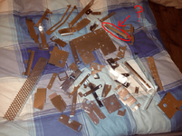
For anyone else restoring the colours I used was fiat red orange and rover inca yellow.
Nice work! Looking great. Sorry if I missed it earlier, but what brand of paint did you use? I'm assuming something like Halfords colour match rattle cans.
For anyone else restoring the colours I used was fiat red orange and rover inca yellow.
Looking at the actual Williams schematics more closely, the System 6 board was used in a few non-pinball machines too. Pin 2 on 3J3 was only used on shuffle machines. The text reads that on flipper machines, 3J3-1 and 3J3-2 are not connected. So that answers the missing black 2 - it's not supposed to be there. The missing red on pin 6 should be there I think. Looking at the schematic, that is the power supply out to most of the coils on the playfield. There should be one common power wire daisychaining between each of your solenoids. That should then go into pin 1 of a big connector, and that should then get to your pin 6 on 3J3.Right guys I need some help with this bleddy loom
I have 2 wires missing on connector 3j3 and none of the schematics or the ones on firepowerpinball.com show where the missing wires go.
View attachment 5393
I have red 7 & 8, missing red 6, blue 4 & 5, black 3 and missing black 2 which is a ground. Can anybody help with where they should go I'm totally stuck till I figure it out.
.......Pinballinfo your my only hope lol
that's miles away from where I allways see the knot in pics lolUsually so if the cord gets pulled from the outside, the wires are not pulled off of their contacts. The knot stops the cord being pulled through the cab cable slot.
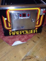
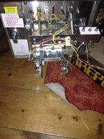
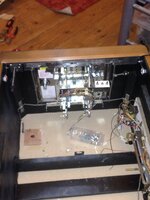
View attachment 5578Right folks I can't remember what piece of metal goes here and it's not in any of my pics doh! Can anyone be kind enough to enlighten me pleaseView attachment 5579
View attachment 5578Right folks I can't remember what piece of metal goes here and it's not in any of my pics doh! Can anyone be kind enough to enlighten me pleaseView attachment 5579
