What's new
Pinball info

Register a free account today to become a member! Once signed in, you'll be able to participate on this site by adding your own topics and posts, as well as connect with other members through your own private inbox!

BSD Opto hell

Rus121

Site Supporter
Joined
Jul 21, 2011
Messages
2,671
Location
Teesside
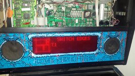
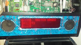
So, my new BSD is a bit of a lemon right now. Got an issue where the game constantly does a ball search. Errors state that #51,#55,#56,#71,#72 switches (all optos) are not working.

I've changed out all the LM339's on the opto 10 board and the ULN2083 @ U20 on the cpu board but the problem persists. I have 15.1v (should be 12v?) going to the 10 opto board. Checked all wiring to optos and back to the cpu and all seems good.

When i unplug the 10 opto board and power the game on, the same problem persists with the same errors. :(

Does anyone have anything else to try before i chuck more money at it?
 
Any battery acid leak?
So basically it's phantom as even with the board disconnected it still shows the errors. Hmmmmmm
 
No acid damage as far as i can tell but it does have a remote battery holder thingy thats croc clipped into the cpu board.

The 10 opto board led doesn't light up yet im getting 15v to the connector. A closer look at the cpu board wont hurt, but its got me stumped right now.
 
If you have volts at the board but no LED then check continuity from the connector 12v and ground to the capacitor c1 and onwards. I would bet that the capacitor c1 has leaked and corroded the tracks underneath it.
 
I just realised there are two +12vdc plugs on the 10 opto board. When i test the one at J3 its 15.1v, when i test the one at J2 There is no voltage present. :hmm: (doh, its from opto boards on PF, lol)

Checked continuity from 12v plug to c1 and it beeps out ok. Into, and out of.

I just removed the cap at C1 and it was leaking a little. Didn't do anything to the track underneath however. Gonna get a new cap tomorrow and hopefully it will come back to life. Maybe. :sad: Really don't want to order a new opto board for this. :(
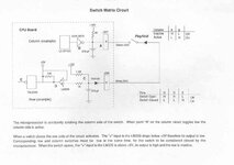
Page 135 on this .pdf if anyones interested:
https://www.arcade-museum.com/manuals-pinball/D/Dracula_Bram_Stoker_OPS.pdf
 
Last edited:
If you've got 12v at one point but not another then it's a case of tracking down the break in continuity. If you've replaced lm339s you may find that one of the 12v pins is used to pass the 12v from one side of the board to another. If poor connection on either side then continuity may be broken. Buzz the 12v out at all points around the board until you've narrowed down the culprit.
 
Ok, it appears i have a really strange issue.

When removing the board to try on my desktop power supply to give it a proper 12v, the LED on the board lights up. When reinstalling the board into the game where i have measured 15.1-15.3v at the 12v pin the LED on the board does not light up. I have checked the IDC connectors continuity and the path to the diode on the board whilst powered in the machine and still, no LED light when there is 15v going to it. I have tested the 10 opto board to the point of insanity continuity wise and as far as i can tell the boards connections are all fine. I even changed the cap at C1 and the LM339's again, and still the issue remains. Hmmmm.

I then test the voltages at the test points on the driver board and i get:
TP1 = 14.45v (AC voltage is rectified to about 12VDC by BR5 and smoothed by C30 to provide unregulated 12VDC power - pinwiki)

TP2 = 4.91v (AC voltage is rectified by BR2 and smoothed by C5. The voltage is regulated down by the LM323K at Q1 - pinwiki)

TP3 = 11.92v (AC voltage is rectified to about 18VDC by BR1 and smoothed by C6 and C7 (this power is tapped for the lamp matrix). D1 and D2 are used to drop the voltage by 1.0 to 1.4V and then the voltage is further regulated down by the LM7812 at Q2 - pinwiki)

I'm obviously going to be pouring over the pin wiki about now, but if anyone has any input at this point, i'd be extremely grateful.
 
Last edited:
The game just reset on me twice in the test menu. As well as manifesting some overly excessive game bulb flickering. :( At this point i'm going to take out the driver board and replace BR1, BR2, BR5, LM323K and LM7812. And probably a connector or two.
 
silly question but do you have an earth to the opto board as you say the led lights on a bench test but not in the game and you say there is 15v there
i suspect you have a data issue with what is going on and the re sets i would try swaping boards from your other machines to pin point the problem then go from there
i once had a demo man with similar issues and would re set every 46 seconds in attract mode turned out to be the driver board but strangely enough worked fine in another game again down to a data issue
 
Agree with Chris. Where is your black lead when measuring 12v on the board? If picking it up in the cabinet you may be missing a ground continuity fault.
 
I was picking the ground up at the front of the cab on the earth strip. Looks like i have more checking to do first......*sighs*

Sadly, i can't remove the driver boards from my other machines without a total meltdown from the missus. I'm already testing her patience with the thing being in the front room and it looking like a pinball machine has exploded there.

Any other suggestions are wholly appreciated.
 
A little background info:

Machine gave opto errors when picking it up from last owner. Upon checking the backbox briefly i noticed a remote battery holder flailing around. by the time i got the machine home, it was completely off the board. It was secured by croc clips so no big deal.
First time i powered it on, the optos not working all appeared to be on a column @ U20 on the cpu board. (#51,#53, #54, #55, #56) It was relatively easy for me to change ULN2083 @ U20 as well as the LM339's on the 10 opto pcb. So thats what i did.
When powering the machine on after reinstalling the boards i get new opto errors at #51,#55,#56,#71,#72. Gives the exact same errors with the 10 opto board unplugged.
 
Tested the ground path to 10 opto board and there is none. Tested continuity from all wires leading to 10 opto from CPU and all are good. Manual pic of circuit:

dracsmc.jpg

Not sure how to test some of those components. Logic probe? Must get me one some day but alas, i am without.

Might have to go with my usual method of complete component replacement? Or send off to someone who can test/repair? (Andy?, Jim?)
 
Russ i think you are getting much deeper in to this than you need
if you have 15v at the 10 opto board and no led on yet the led is on when bench tested this sayes to me that you have no ground to the 10 opto board i think this is your main problem you need to check this i would suspect you have a broken wire somewhere
 
Lol. Yeah, perhaps. Thing is, i've checked everywhere for wires off and they are all connected as they should be. Maybe i'll just sit back and think about it for a bit...
 
looking at the manual now the 10 0pto board takes its ground and power from j118 on the driver board be care full as it may have been swaped to j117 or116 but will make no diffrence all the same voltages you need to meter these down to the 10 opto board or just check the connectors anyway or maybe a bad solder joint on pins
 
After some faffing with all the wires, checking again. It seems i now have power to the opto board and the optos errors are gone. The error i get now is "ground short - row 4 - white yellow". Argghh! lol.
 
Its J208 instead of J209 on this machine for some reason? Anyway, i disconnect J208 and the ground short issue goes away, but i get back the opto issues described earlier but this time just switches #51, and #73 dont work along with the 'ground short -row 4 - white/yellow' error and top right ramp up error.

So i guess im looking for a short on the PF?? Head is fried.....lol.
 
Last edited:
Ok, will have a bash at that right now. Obsession creeped right in. haha.
 
Back
Top Bottom