Pinball info
You are using an out of date browser. It may not display this or other websites correctly.
You should upgrade or use an alternative browser.
You should upgrade or use an alternative browser.
BSD Opto hell
- Thread starter Rus121
- Start date
So, i disconnected all the white-yellow wires from each item in line and these are the results:
Left sling switches = Ground short row 4, top right ramp up error
Plumb bob = Ground short row 4, top right ramp up error
Launch ball = Ground short row 4, top right ramp up error
Trough 4 balls = Ground short row 4, top right ramp up error
opto castle 2 = Ground short row 4, top right ramp up error
Left ramp score = Ground short row 4, top right ramp up error.
As you can see after disconnecting the lot and I still get the ground short, top right ramp up errors.
- Joined
- Jul 21, 2011
- Messages
- 2,527
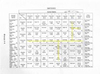
It's not as easy as that to say that the fault is on the playfield. You need to disconnect the rows and columns connectors from the cpu then replicate each single switch in turn by shorting row 1 pin to each column input in turn then repeat with row 2 etc. Each short should give you one switch closure. If you get multiple switch closures with a single pair shorter then the fault is on cpu. If Only single switch closures are seen then the fault is playfield.
- Joined
- Jul 21, 2011
- Messages
- 2,527
Yes. But you don't really need to use a diode. Any wire will do.
Took a while but i got there. Disconnected all but J205. Connected pin 1 of J207 to pin 1 of J208, then pin 2, pin 3 etc. Then did the same with each pin on J207. Every single switch came up with no double switches. Looks like a PF issue then i guess?
Last edited:
Ok so you have ruled out the CPU solder all the yellow and white wires back on make sure you solder them back to the un banded end of the diode
Have a good look round all the switches particularly ones that get hammered and report back
Another way you may be able to narrow it down is to connect CPU up as normall and remove each column wire green one at a time if the row short goes when one of the column wires is removed then this should narrow it down to what column the short is on
Hope this makes sense
Cheers for your help Chris, its most appreciated. 
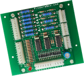
This morning i took delivery of a new 10 opto board from ministry of pinball. Installed it, powered on, and now have multiple ground short errors as well as some new switches not working and the ramp up error. I then replace the board with the old one and the new ground shorts go away but come back with the ground row 4 error again. Uplugging the 10 opto board and i get no ground short errors at all, but new errors in #16,#25,#26,#35 and a top ramp up error. At this point i suspect something going on with the CPU board so instead of torturing myself anymore, i am going to send it in to Andy (tried to get the post today, but failed. I'll get it sent off tomorrow now) for a good check over. I lack the equipment to properly test it and i hate not knowing, so off it goes.
Whilst the CPU board is away i will go over the driver board and make sure its all in tip top condition before turning it on once the CPU comes back.
The machine wont win. My need to play it grows with every error.

This morning i took delivery of a new 10 opto board from ministry of pinball. Installed it, powered on, and now have multiple ground short errors as well as some new switches not working and the ramp up error.
Whilst the CPU board is away i will go over the driver board and make sure its all in tip top condition before turning it on once the CPU comes back.
The machine wont win. My need to play it grows with every error.
Bit gobsmacked it's €79.95 or about £72. It's got 3 x KA339 comparators (35p each), 31 x 1/2W resistors, 10x 2W resistors, 13 x diodes, 1 capacitor, 1 LED and 6 header sockets. I'm looking into starting up a cottage industry making replacement boards like this for much more reasonable prices. Just experimenting with a couple of small Bally expander boards.
Sorry, I'm not helping this thread Good luck! Looking forward to finding out what the root issue is...
Sorry, I'm not helping this thread
- Joined
- Jul 21, 2011
- Messages
- 2,527
Cpu is good. (As received)
- Joined
- Jul 21, 2011
- Messages
- 2,527
I'll send cpu back today. As the chips in the new 10 opto board are socketed, you could remove them one at a time to isolate the chip that is giving you the error. It may be that you have a short in playfield that has popped the new chip on the opto board. If you can further narrow it down to specific wire then a close examination of that wire around the playfield may reveal a short potentially to a solenoid voltage.
I 've looked at the wiring till i'm blue in the face. As far as i can tell, there are no two wires touching, no wires touching ground, or solenoid voltage coming anywhere near the wires that go into and out of the 10 opto board (or anywhere else)
Its a real mystery, but i hope to get stuck in once the CPU comes back. I will try what you suggest Andy, because at this point, i'm screwed and don't know what to do with it. First time ever a pin has me this puzzled. Its not a good feeling.


If it tortures me for much longer i will have to rewire the thing.
Its a real mystery, but i hope to get stuck in once the CPU comes back. I will try what you suggest Andy, because at this point, i'm screwed and don't know what to do with it. First time ever a pin has me this puzzled. Its not a good feeling.


If it tortures me for much longer i will have to rewire the thing.
Thanks for the offer Jon, but its gone back to the previous owner to diagnose. Hopefully, he will be able to get to the bottom of it.
I must say, there are some really good people in this hobby. Thanks to all who responded in this thread, but special praise to the previous owner who went above and beyond to help me out on this. I'll update this thread once the issue has been located.
I must say, there are some really good people in this hobby. Thanks to all who responded in this thread, but special praise to the previous owner who went above and beyond to help me out on this. I'll update this thread once the issue has been located.
It will be fixed tomorrow
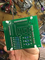
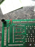
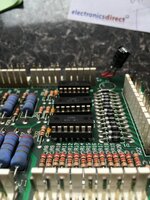 Ok time to put this one to bed
 Started with the original 10 opto board on close inspection the capacitor had leaked and spread to the switch matrix diodes and some poor repairs meant only fit for the bin really
Ok on to the new Pandora board this had 3 three rows shorted to ground on closer inspection and some testing found design error on the board as there is no track to link to the resistors so had to make one see pic
Soon as I jumped it all was good
So really down to inexperience and a poor quality board we need Jim at my pinball to start producing more quility boards
- Joined
- Jul 21, 2011
- Messages
- 2,527
Good work Chris. I don't know this board so only have your pics to work on. It looks to me that the link to the resistors may be via the lead of the electrolytic capacitor. If this has been poorly sourced soldered in, then it may not be picking up the trace between capacitor and board.
Bert is a nice guy
I would suspect all the boards will be like this
It looks a pretty much copy of the original board to me the 339 where difrent
I would suspect all the boards will be like this
It looks a pretty much copy of the original board to me the 339 where difrent
I guess someone took it upon themselves to get them made:
http://www.ebay.co.uk/itm/Pinball-M...047319?hash=item4b0f86ea97:g:LH4AAOSwjDZYcSLk
Non soldered? Should be a tenner.
http://www.ebay.co.uk/itm/Pinball-M...047319?hash=item4b0f86ea97:g:LH4AAOSwjDZYcSLk
Non soldered? Should be a tenner.

