OP
OP
Cheers


")
It does all boot up as I had the board set fixed and working
Just noticed the cone has perished on the cab speaker. Do I have to buy a Williams speaker or can I buy a car one? If so what type do I need?


.JPG")
.JPG")
the force is strong with you well in your trousers anyway
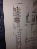
Right gone back on to the looms doing the cab one at the mo as it seemed the easiest. Now on this mini loom there's deff a jumper wire missing on this connector for some reason I don't question the bizzarness with this machine anymore I just shake my head and put it back to factor anyway I digress. The jumper that is there is in the wrong position isn't it? Or am I misreading the drawing. Dyslexia and schematics don't mix lol.
View attachment 4586
View attachment 4588
Right think ive got to the bottom of the cab loom only prob ive come across which im not sure about is on the coin door side of the short coin door loom there are 5 wires cut off at the connector. One grey and black you can see in my pick just looks like a ground just screwed to the door (cant even see that on the wiring diagram), 3 are for the center and left coin mech which it doesn't have anyway so not bothered about that but the last one red is ment to go to the coin lock out but I have no idea what that is can anyone help please? Also as you can see in my pic there are 2 replacement wron coloured wires yello and a grey one attached to the 2 coin mech leaf switches the other end of thoughs wires are connected to nothing. Any idea what colours they are replacing so I can connect them up. Heres the link to the wiring diagram http://www.firepowerpinball.com/downloads/CabinetWiring.pdf
View attachment 4589 View attachment 4590