What's new
Pinball info

Register a free account today to become a member! Once signed in, you'll be able to participate on this site by adding your own topics and posts, as well as connect with other members through your own private inbox!

In Progress Firepower Shop Log

Sorry, @RudeDogg1! My comments were about real auto 2k from a bodyshop on playfields, and not your work on this FIREPOWER. Topic for a separate thread really, not cluttering up your shop log :oops: I'm rather impressed with what you've done on FIREPOWER! You can level my inserts any time ;) As I mentioned way back in August last year (where has the time gone?) I'm going to be using the same rattle can lacquer on my PARAGON overlay (when I eventually get around to it!)

I guess it's all a balance and different for each project. There might be an ideal way to restore playfields (like all the vid1900 stuff on Pinside) but we all have varying amounts of time, facilities, resources and money to do it. We make compromises and balance effort against results; aesthetics against practicalities.
 
Sorry, @RudeDogg1 I'm going to be using the same rattle can lacquer on my PARAGON overlay (when I eventually get around to it!)

I would be cacking myself clearcoating over the top of that lovely Paragon overlay. I like the overlay you've made for your Gold Ball, would that method not be a safer bet?
 
I would be cacking myself clearcoating over the top of that lovely Paragon overlay. I like the overlay you've made for your Gold Ball, would that method not be a safer bet?
Depending on how my experiment with GOLD BALL goes it could be distinct possibility!
 
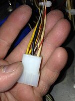
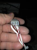
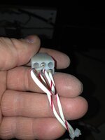
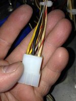
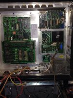
Well I've put the boards back in and luke is gonna guide me step by step testing etc so I don't blow the boards lol. I've already noticed a connector that don't match the drawings http://www.firepowerpinball.com/downloads/CabinetWiring.pdf

img.photobucket.com_albums_v393_RudeDogg1_Firepower_20Project_IMG_2885_zpsnfzbm8jr.jpg


img.photobucket.com_albums_v393_RudeDogg1_Firepower_20Project_IMG_2886_zpsxjyin1e4.jpg

Do you think the 2 yellows and 2 white reds should be doubled up so they are in 1 pin each?
 

Attachments

  • IMG_2886.JPG
    IMG_2886.JPG
    60.6 KB · Views: 2
  • IMG_2885.JPG
    IMG_2885.JPG
    86.6 KB · Views: 2
Well I've been forgotten about since "skitball****" lol

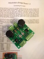
Anyhow just ordered one of Peters (iinkognito) bridge rectifier boards so if anyone is after one of the huge blue capacitors give me a shout
 
Just installed this bad boy

tapatalk.imageshack.com_v2_15_03_28_20a108ffb268789e23e5f06170c55d29.jpg

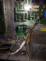
Very straight forward to fit using the instructions some machines such as firepower use less wires and some are a different colour than on his williams Walkthrough mine doesn't have the connector it shows either.

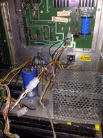
Before

tapatalk.imageshack.com_v2_15_03_28_7fa7d5d341a9abe543c15fb6da918d1f.jpg

After

tapatalk.imageshack.com_v2_15_03_28_364134e8327ba58fbb5df701e351567e.jpg

tapatalk.imageshack.com_v2_15_03_28_e7d2d6eb9799f673d25a8490b360a48a.jpg
 
Well not really off to a good start all that's connected at the mo is power to the transformer and the 2 transformer connectors to the power board. All voltages from the power board pins are reading on the low side so something isn't right somewhere
 
Not to hi-jack thread but finishing off my Firepower today ready for The Welsh Pinball Cup. Great game. Looks better with LED's (superbright). But have lost his speech....sob.
I have some spare plastics, bumper caps and other parts left over. All parts for sale.
 
well seems 2 out of the 3 multimeters was foobered including a new one which is why my voltages were reading low grr lol. Just waitinbg for luke to return so I can progress further
 
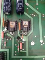
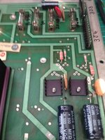
Well this machine is being a right ball ache the display voltage is to high even when under load. After realising I had in fact already bought a hIgh voltage rebuild kit ages ago I decided to replace all components I hadn't already replaced.

Before
IMG_2945.JPG

IMG_2946.JPG

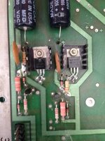
After I'm really not happy with the way you have to install the substitute transistor is there a batter way to do it? Shame you can't just stand them up because it's like not enough leg reaches through the hole

IMG_2951.JPG

After all that it's the same if not a Lil worse hopefully just caused by one of the new trannie being shorted!
 
Sooo.... Some of you will be pleased to know I have got back on to this project. Its so bloody frustrating I seem to take one step forward and about 10 back. Luke had the powerboard because the HV section was knackered. I had the displays working about 95% but then the master display decided to blow the hv again grr. So I managed to get a "working" master display and got a x-pin power board from Phil for ease. So now all the boards work and the cpu boots but have zero life in the any of the displays. All the voltages from the master display connector meter fine so now im stuck again. So bloody close all ive got to do is get them working then start connecting the playfield grrrr "sobs"
 
Some of you will be glad to hear I've got back on to this project after Luke wells fixed the powerboard. So anyway I had the displays working 95% then it looked like the master display took out the hv section of the powerboard. So I ended up buying a less reworked master display from the forum. And bit the bullet and got a xpin powerboard from Phil just for ease. So now I have all boards working, CPU is booting but zero displays all I've got is on the 4 displays is a lil round orange glow on the bottom of each one. What should I do now? I was thinking of replacing all the diodes on the master because I read that they can be a problem plus a couple have been swapped before
 
I wonder if you have a bad blanking signal (bad loom connector from CPU 1J3 to master display 4J6-3)

Check continuity with power off and (carefully) give them a wiggle with the power on (keep fingers away from high voltage)
 
Holy crap Rudi is this still going?
Ok TTT time out

Wtf is going on here. Why is it still not working after 2 years?
 
Luke had the boards for quite a while (he's a busy man) and I didn't touch it for ages. It's finished really it's just getting the electrics to work altogether that's left.

You've got to remember every board was fooked despite it being sold as "all boards rebuilt and working" so god knows what other faults were lurking
 
The board and electric stuff ain't my strong point so dunno but I want it finished ASAP. I was foolishly thinking the new powerboard and replacement master display would miraculously sort everything out so I could start connecting pf connectors
 
I wonder if you have a bad blanking signal (bad loom connector from CPU 1J3 to master display 4J6-3)

Check continuity with power off and (carefully) give them a wiggle with the power on (keep fingers away from high voltage)

Tested today and it has continuity, also tested the 2 100v test points on the master and got 90v on each (I assume this is because they use a lower spec transistor on the powerboard to protect the displays).

Also tested the resistors because I read they can be one of the probs. For some reason I can't get a reading on r15 - 19 on both the original master display and the replacement one surely they can't be dead on both?

uploads.tapatalk_cdn.com_20160501_6cd3acb8292915bd2bfac188ce486c32.jpg
 
If you can't get a reading on a resistor, then it's open circuit (assuming your meter cost more than a fiver ;) ) so replace away
 
Back
Top Bottom