My first ‘fixing it’ documentation for you guys, I now have 3 games, 2 of which are machines in various stages of ‘getting there’.
Magic Circle – 1960’s Bally EM – Working but in need of a total overhaul.
Mr & Mrs Pacman – 1980’s Bally SS – Bought as a box of bits minus cab.
Firepower – 1980’s Williams SS – Bought from Andy on here.
Only been in the game a few years and got into it as I have always liked tinkering and finding solutions to problems, electrical and mechanical.
My history of pinball abuse can be found at the following locations if you are so inclined.
Magic circle story can be found here….
https://pinside.com/pinball/forum/topic/bally-magic-circle-semi-sympathetic-playfield-restoration
Pacman story can be found here…
https://pinside.com/pinball/forum/topic/mmpc-first-ss-second-pin-coffee-table
Chapter 1 - Introductions
I’m going to start this off with a warning. This is not going to be a quick project. My time is limited and I have to priorities it in the following order…
Money making Job
2 Boys under 5
2 other machines
This machine
House maintenance
Wife
I am also relegated to doing anything productive outside as space is limited meaning that at this time of year, with the light limited, I am not going to be doing much more then scratching the surface of this project.
So with all that out the way…ONWARDS
This machine has been around a bit. It was originally sold by @johnparker007 to @andy and Andy ended up selling it on to me. Both I gather had intentions of doing it up with the included NOS playfield but in both occasions their missions failed. Is this a jinxed machine, well it did take 2 months for Martin’s BIL to deliver it so it may well be. (Martin was 100% sympathetic to my plight)
Know History: Machine boots into test mode if playfield is unplugged. Plugging in playfield causes playfield fuse to blow.
Initial Findings
.jpg")
Bottom cabinet Internal


.jpg")
.jpg")
Backbox External

.jpg")
Backbox Internal
.jpg")
.jpg")
Backglass
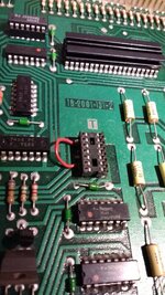
Boards


.jpg")
.jpg")
Original Playfield Topside


.jpg")
.jpg")
.jpg")
.jpg")
Original Playfield Underside

.jpg")
.jpg")

Generally happy with the machine, bought it as a project and that is what I got. It looks like the machine has had some investigative work done on it, the backbox has been dropped and the GI lamps have cooked the plastics. Someone has tried to rectify this by improvising giant resistors out of galvanized fencing wire.
Sounds like something we can get our teeth into.
Firepower Photo Album
https://1drv.ms/a/s!Aqp7OhVuaaqngeVUA0SC3fuZotO4Bw
Magic Circle – 1960’s Bally EM – Working but in need of a total overhaul.
Mr & Mrs Pacman – 1980’s Bally SS – Bought as a box of bits minus cab.
Firepower – 1980’s Williams SS – Bought from Andy on here.
Only been in the game a few years and got into it as I have always liked tinkering and finding solutions to problems, electrical and mechanical.
My history of pinball abuse can be found at the following locations if you are so inclined.
Magic circle story can be found here….
https://pinside.com/pinball/forum/topic/bally-magic-circle-semi-sympathetic-playfield-restoration
Pacman story can be found here…
https://pinside.com/pinball/forum/topic/mmpc-first-ss-second-pin-coffee-table
Chapter 1 - Introductions
I’m going to start this off with a warning. This is not going to be a quick project. My time is limited and I have to priorities it in the following order…
Money making Job
2 Boys under 5
2 other machines
This machine
House maintenance
Wife
I am also relegated to doing anything productive outside as space is limited meaning that at this time of year, with the light limited, I am not going to be doing much more then scratching the surface of this project.
So with all that out the way…ONWARDS
This machine has been around a bit. It was originally sold by @johnparker007 to @andy and Andy ended up selling it on to me. Both I gather had intentions of doing it up with the included NOS playfield but in both occasions their missions failed. Is this a jinxed machine, well it did take 2 months for Martin’s BIL to deliver it so it may well be. (Martin was 100% sympathetic to my plight)
Know History: Machine boots into test mode if playfield is unplugged. Plugging in playfield causes playfield fuse to blow.
Initial Findings
Bottom cabinet External
- Structurally sound, usual knocks and dents found on any wooden box of this size and age
- Joints and surrounding paint not showing any signs of stress or strain that I would expect if the box had been dropped or twisted.
- Section missing from bottom lip on rear chipboard panel. Andy included the missing bits.
- Paint not showing any signs of fading.
Bottom cabinet Internal
- Dirty. Nothing a wipe down wont initially fix.
- Standard rust on lockdown bar receiver.
- Speaker a little corroded.
- Power switch relocated then removed.
- Improvised relay circuit to trigger 2 counters.
Backbox External
- Solid but slight movement in joints. Top right hand corner is slightly separated and shows symptoms of being knocked or dropped.
- Additionally it has the usual signs of abuse for a bit of furniture of this age.
- Paint not faded.
Backbox Internal
- Display panel crooked, as if it has been hung on when open, or maybe from a drop.
- Trim and locking mechanisms look ok.
- Everything is labeled. To me this indicates some troubleshooting has been done.
- Galvanized fencing wire added to GI line on back of display board.
- GI line to display board patched to bypass original connector.
Backglass
- No cracking and only a minor bit of black missing from around one of the displays.
- Not pure white on the backside but I don’t know what it should look like.
- It may be a different story once it is lit up in the box but it is a good starting point.
Boards
- 40pin connector replaced with a birds nest.
- Batteries relocated into remote pack.
- Some signs of board work but nothing major.
- Standard things such as resistors and caps replaced.
- Driver board burnt under resistor bank.
Original Playfield Topside
Guess it is the expected wear for this game but the top end of the playfield has been hammered by the top kickout hole.
Original Playfield Underside
- Galvanised fencing wire added to GI line.
- Mechanisms all rust free but all lubricated with oil.
- All kicker mechs seized up as oil has hardened.
- Spinner link installed wrong way round.
- Lamp sockets all have additional wire jumpers from solder tags to main lamp body.
Plastics
Most are cooked by the GI lamps.
NOS Playfield
- Showing signs of age and a lifetime outside a game.
- Slight planking, not lifting but the wood drying / ageing has split the paint.
- Screen printing is misaligned.
- White is yellowed. This is probably due to the protective layer on the playfield reacting with light.
- Inserts all whole, transparent and imperfection free.
Generally happy with the machine, bought it as a project and that is what I got. It looks like the machine has had some investigative work done on it, the backbox has been dropped and the GI lamps have cooked the plastics. Someone has tried to rectify this by improvising giant resistors out of galvanized fencing wire.
Sounds like something we can get our teeth into.
Firepower Photo Album
https://1drv.ms/a/s!Aqp7OhVuaaqngeVUA0SC3fuZotO4Bw
Last edited:

 I'm predicting that no airbrushing will occur indoors this time