What's new
Pinball info

Register a free account today to become a member! Once signed in, you'll be able to participate on this site by adding your own topics and posts, as well as connect with other members through your own private inbox!

In Progress Firepower – From Powerless to Mission accomplished

Old bayonet sockets are a right pain.

Purists say "just change them all". This is a lot of work and actually quite expensive. Andy at Mania stocks the holders.

I tend to give them a clean in situ. Then if they fail again, I change them. Sadly these things tend to keep going wrong which is why the purists say what they do.

To clean them.

  • Isopropyl alcohol - spray it in the socket and remove the filth with a robust rolled up cloth that does not leave lint everywhere.
  • Use a Brad point wood bit to clean the top of the spring at the bottom (Bally games have these, I do not know about Williams ones)
  • Use a rolled up piece of scotch brite pad (like a plastic version of wire wool) to clean the inside of the bayonet. Some folk attach this to a drill or dremel to give the cleaning some oomph.
  • You can use a dremel in there too with the right end on it but this can be brutal
  • Don't forget to clean the bayonet slots as this can be the main contact points for the bulbs. Rolled up wet and dry should do it
  • Clean the bulbs too - ipa of they are in good condition. Very fine wet and dry as well if they are corroded, especially the bottom contact
All in all a loathsome job I am afraid. Cleaning them is horrible and you often have to do it again. Replacing them is expensive and horrible.

Best thing is to get some other cünt to do it, if you can find one.

Good luck
 
  • Bypass the sodding press-fitting contact points altogether and solder to the 'nipple' part on the very bottom, and onto the side of the socket. Then there is at least only solid metal between the wires and the socket; and the only surfaces you have to keep electrically clean are the areas around the bayonets of the bulb, and the internal spring-loaded seat. The existing press-fitted solder tabs do nothing but add another potential failure point.
  • If rust is a concern, grit your teeth, remove all of the sockets and give them a vinegar bath. Rinse off several times with water and dry out thoroughly, and quickly. It isn't going to get any worse after that unless you deliberately keep your pinball wet. It beats the hell out of mechanically trying to clean them in situ even at the cost of resoldering, but it's easier to accept if you consider that you really need to redo all the solder joints anyway for a proper job. However if the sockets are dirty you may not be able to avoid some elbow grease. If you're the kind of guy that has an ultrasonic cleaner, you don't need me teaching you how to suck eggs.
  • Yes, it sucks dealing with them. I removed my playfield in order to be able to tolerate working on all of them properly. Whatever you need to do in order to be happy doing them all properly; do it. It's worth it.
 
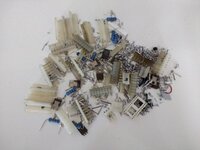
Generated this pile over the last few days...
Scrap pile.jpg


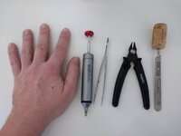
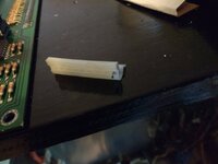
All headers and stuff to be replaced has been removed from the MPU/CPU board and the driver board. No fancy toys used just these tools...
Desoldering tools.jpg

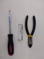
Header tools.jpg

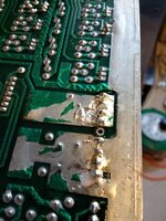
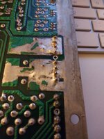
You can see from the first pic that a lot of the headers just dropped out once desoldered. Any headers that did not drop out were re-soldered (to add strength), using wire cutters the pins were cut off as close to the base as possible and the nylon base was the lifted off the remaining pin stubs using a screwdriver as a leaver. A piece of card protects the PCB from damage. I found a socket screwdriver best as it had a thicker shaft and offered better leverage.

Over this process it was amazing how many pins had cracked solder joints and were not retained. I'm surprised the game worked at all.
Broken Joint 2.jpgBroken joint1.jpg

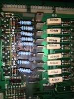
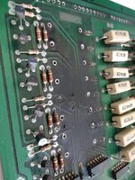
The resistors and transistors from the lamp blanking are were also removed, going to be replaced with zero ohm resistors and IFR9Z34N MOSFETs. In the after picture you can see where the board has almost been burnt through. All the traces test out so should be good to rock once finished.


Resistors before.jpg

Resistors after.jpg

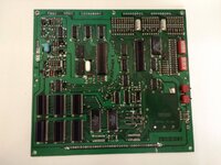
So this is where the board are now. 40 pin replacement still outstanding but I have some test parts arriving soon.

MPU without headers.jpg

Driver without headers.jpg
 
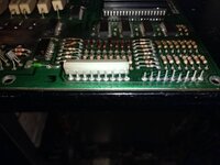
Replaced all the headers on both CPU and Driver board. Rebuilt resistor and Mosfet blanking section.
DriverBoard new headers.jpg

CPU new headers.jpg

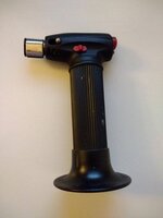
During this process I had some real problems getting heat into solder joints where the headers mounted to any substantial mounting areas like the ground track. I got a 12w soldering iron for small project work and a 18w to 150w gun for heavy work but even the big boy had issues, I think due to different solder types being used over the years. I fought on but was not happy with the resulting mess so I ended up using a new tool. A kitchen blow-torch...
Blowtorch.jpg

Before mess...
Poor solder 1.jpg

After mess...
Poor solder after.jpg

The results are far from perfect and its a risky process but the end product it sound.
 
Finally finished the CPU and Driver boards including the 40pin header. Ended up getting the 40 pin parts from mouser. As the replacement header pins were shorter then the originals I have put some washers behind the lower CPU mounting bracket ( the hook under the 40 pin connector ) to bring it forward a few millimetres and I added some insulation tape to the back of the Driver board to avoid any shorts to said bracket as the boards are now closer together. Also de-burred and wiped down the left side of the back-box. Need to find a few more mounting screw to replace missing ones.
Finished CPU:Driver.jpg

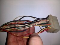
So one job down and another presents itself, removed some cable ties from the 36 pin molex bundle to aid cleaning and found many of the cables were damaged from being pinched somehow, most of them have damage, here are the ones visible from this angle. I have a pin remover but not sure if it will work on this connector. I may have to cut the whole cable back and re-pin if i cannot pop the pins and slide heat-shrink over.
Chewed cables copy.jpg
 
Upon further inspection it seemed the the cable may have been caught up on something and consequently some of the bundle was pushed up against the reset resistor back thus melting the cables.
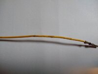
Here is a sample and the spacing, other cables showed sighs of being cooked at the same intervals but the insulation was still intact.

Damaged cable.jpg

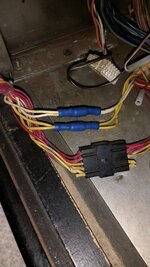
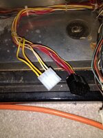
I also added a 5 pin molex of a higher rating to the backbox GI line to replace the crimp connection bodged before. I decided against trying to re-pin it in the original plug as the wire length was too short meaning it would be under constant tension.

Before
Old backbox GI.jpg

After
Bodges backbox GI.jpg
 
Progress....
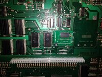
Tarted up the NVRAM install and made sure the new 40pin inter-board connector was seated properly.
NVRAM 40pin.jpg

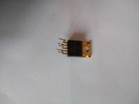
I managed to cook the amp TDA2002. I got two new ones from here... (
https://www.ebay.co.uk/itm/TDA2002-...e=STRK:MEBIDX:IT&_trksid=p2057872.m2749.l2649 ) ..they arrived next day.
DeadAmp1.jpg
This is the offending dead one showing no signs of abuse.

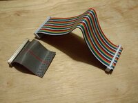
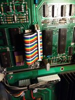
Also replaced the ribbon connector to the speech board. Used a Raspbery Pi3 connector ribbon that I had laying around at work..
Ribbon cable replace1.jpg

Installed ribbon.jpg

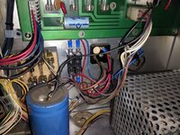
Finally also got the fuses installed on the bridge-rectifier AC supply lines as is recommended for fire prevention. At a later date I will also fuse the 'special' solenoids to prevent board damage should a switch fail closed.

Rectifier Fuses1.jpg

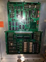
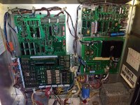
Installed all boards using PC cabinet screws with star washers, I had loads of these and they are nice and secure. So all the boards have had headers and connectors done now, the cabinet has had a wipe down inside and we boot up and have all game functions working with sound and speech. Party on, time to get this thing setup somewhere and give it a bashing to identify anything else to fix in the back-box.
Backbox Together1.jpg
 
Other stuff done, just for fun...
De-burred the whole of the inside of the backbox.
Moved GI fuses 5cm to the left to make room for new fuse holders.
Removed rectifiers, de-burred mounting holes and re-seated with heat transfer compound.
Re-seated the big capacitor by transformer as it only had one screw hole aligned.
Exposed and removed transformer, cleaned off crap and dust.
Re-hung backbox display board as it was crooked.
Cleaned all lamp sockets with dowel and sandpaper.
Installed all playfield and backbox lamps.
 
Thrashed it on and off for about 6 hours. Checked temps in the back-box and nothing seemed above the Google norm but I would still like to find a way of removing all the power resistors from the driver board.

Only issues identified...
I forgot a bulb under No.6 orange arrow.
1 and 6 targets needed adjusting.
2 GI bulbs needed rattling, guess I need to clean the sockets better.

Apart from that I'm well chuffed, never worked on this make or age before and no board faults after a complete re-pin, mega happy.
 
An intermittent problem has popped up.

Randomly on power up the game has no sound, none at all. If the self test button on the sound board is pressed all sounds and voice work. Voltages also read ok.
After replacing the ribbon cable a while later I started getting intermittent sound but I identified that as one of the ribbon cables had un-seated itself. I have also replaced the volume control pot in the lower cab.

If the games starts with sound the audio remains working (tested for 4 hours).

Anyone have any opinions ?
 
Try booting it, leaving it on for a few mins, (so capacitors are fully charged), then flick off/on - if it works every time following that sequence, you know it’s a probably a cap issue. I read this somewhere recently.


Sent from my iPhone using Tapatalk
 
Try booting it, leaving it on for a few mins, (so capacitors are fully charged), then flick off/on - if it works every time following that sequence, you know it’s a probably a cap issue. I read this somewhere recently.


Sent from my iPhone using Tapatalk
Good idea.
I have all the capacitors ready to replace, got them from USA when I ordered the 40pin parts to bulk up the order to meet minimum spend for free P&P
 
Back
Top Bottom