What's new
Pinball info

Register a free account today to become a member! Once signed in, you'll be able to participate on this site by adding your own topics and posts, as well as connect with other members through your own private inbox!

Bally invaders voltages

Body pop

Registered
Joined
Feb 23, 2015
Messages
212
Location
Belfast
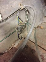
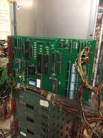
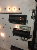
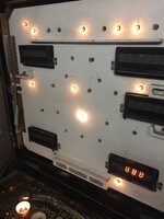
Can any of you guys give a run down on how and where to check the voltages on this old space invaders please ,
I was wanting to check first of all the voltages straight from the power supply or at least a point with no boards attached .
Thanks in advance
 
I’ve measure the voltages at the power supply
Test Point 1. 7.0
2. 227
3. 13
4 . 6 ac ?
5 39

Do these sound right to start with ?
Turning the machine on I just get some lights on playfield and backbox
It’s not booting or attempting to boot .
I’ve coin door off it at the min ,would that make a difference to it attempting to boot
I’ve got an altek replacement mpu board as the one in it looks bad
What would be my next step please
 
Yes. Good enough. Now repeat for the 12v and 5v test points on the power driver board (top right) and mpu ( top left)

Andy
 
Solenoid driver board is
Just point 1 . 4.1 v
Point 5 . 8.6 v

Not sure about the mpu it seems all over the place .is there a ground on the mpu

Thanks again
 
don't forget to check the HV section of the solenoid driver board as well,it's quite a common fault for it to be blown and feeding 240v to the displays instead of around 180-190v,the displays will still work,but burn out a lot quicker due to the excessive voltage
 
You won’t get voltages on the mpu until you get the voltages on the driver board sorted. You need 12v to arrive at the driver board where it’s converted to 5v for the mpu.

Suspect the connector top right of the driver. Find where the 12v arrives in that connector and why it doesn’t make it onto the board. The 12v input pin is often blackened and makes poor contact on the connector. It’s somewhere just above half way down I think [emoji848]
 
I’m now getting 11.7 - 11.8 at the driver board
All I done was reseat and clean the pins a bit
I’m getting 193 at test point 2
A49046D7-1357-4916-BE93-AD7AC7EB677D.jpegA49046D7-1357-4916-BE93-AD7AC7EB677D.jpeg2BD1359C-C153-4943-B7D9-9D73B0617C14.jpeg
 

Attachments

  • 392EC147-9FA4-4320-A73E-6AFD886EE8FC.jpeg
    392EC147-9FA4-4320-A73E-6AFD886EE8FC.jpeg
    122.3 KB · Views: 13
  • 7843EB41-ADA3-4FF9-B7AA-E19C70E19751.jpeg
    7843EB41-ADA3-4FF9-B7AA-E19C70E19751.jpeg
    65.2 KB · Views: 12
your hv section is good then,so that's one less thing to worry about,I would test the voltages on the mpu loom plug with it disconnected from the mpu board,that way you can tell if the plug is ok,or if it's the loom/header pins on the driver board,you can insert pins used for sewing in the mpu plug as a temp fix to test voltages,if your multimeter probes wont make contact with the back of the plug pins,although power down before you fit/remove them obviously,as if you ground them,your fuses will go bang
 
Thanks mate ,when testing that loom do I just put the black of the metre to the ground strap on back box .
 
Here looks to be some of the culparates.these wires are wrapped together and taped in places ! 5A7BC457-046F-4DD2-9A9C-9F08C44C9F0F.jpeg
 

Attachments

  • FFDB3019-2F3A-42C7-881F-EB4BCC62B690.jpeg
    FFDB3019-2F3A-42C7-881F-EB4BCC62B690.jpeg
    82.8 KB · Views: 19
  • 1AB2C55F-05C5-4B8F-BA87-01601E82A60A.jpeg
    1AB2C55F-05C5-4B8F-BA87-01601E82A60A.jpeg
    129.4 KB · Views: 19
  • 91375127-A095-4E5A-A329-4AB94088C377.jpeg
    91375127-A095-4E5A-A329-4AB94088C377.jpeg
    100.5 KB · Views: 17
  • B07FF886-FFF2-498A-B61A-9C70EF4BEC64.jpeg
    B07FF886-FFF2-498A-B61A-9C70EF4BEC64.jpeg
    85.8 KB · Views: 16
Thanks mate ,when testing that loom do I just put the black of the metre to the ground strap on back box .
yes that should be fine,looks like that connector has been botched in the past by someone
 
Hello, I'm not quite sure from the pictures, but is the Mpu board grounded, by screws at the bottom left and top right corners? I've not looked into the Alltek replacement, but it looks as if it should follow the original in this regard. All the circuit boards, except the displays, ground to their metal frames

Edit - the front door not being fitted wouldn't affect the ability to boot up
 
It’s probable that the pins inside the connector that is botched, are broken. You can pop them out by inserting a point into the side to push the barb down and pulling the pin out. It should be obvious if the pin is in good order or not.
 
Small bit of progress made , I took some of the pins out and cleaned them
Then mpu boards green light flicked 7 or 8 times
There was a click from the solenoid board I think
But nothing else ,it seemed to go through the sequence again.
Not get the green light anymore ,so presume I will have to change the pins ?
 
sounds like it is resetting after it's boot sequence,this can be down to dodgy connectors,so no harm in replacing your botched one
 
Thanks Steve ,don’t suppose you or pinballania have any links to buying the set of conectors and pins ?
 
im pretty sure andy(pinballmania) does them,as do swallow amusements
 
Can anyone tell me where this big ground should go please
 

Attachments

  • F27DF602-C828-40FF-8D30-BF7E6C01A00C.jpeg
    F27DF602-C828-40FF-8D30-BF7E6C01A00C.jpeg
    114.9 KB · Views: 15
  • ECDA1C9F-C110-47B5-9D08-4394C7131C86.jpeg
    ECDA1C9F-C110-47B5-9D08-4394C7131C86.jpeg
    80.4 KB · Views: 14
  • C38497E7-05D3-4EAD-8440-D93AF2C9B625.jpeg
    C38497E7-05D3-4EAD-8440-D93AF2C9B625.jpeg
    83.5 KB · Views: 14
Here
4d8ad21785560f2c4ad3e28f149f6b4f.png
 
A bit of progress with this ,I replaced the connector on the hacked mpu switch
I’m getting power to it now
It’s flashing 7 times .
Does that mean it’s booted ?
What would be my next step ,there’s a few numbers on the score boards
 

Attachments

  • E5353D8F-D312-44B0-93B7-27FB82D7303B.jpeg
    E5353D8F-D312-44B0-93B7-27FB82D7303B.jpeg
    123.5 KB · Views: 14
  • C8949032-8B55-4CCE-8AA6-734FF4242498.jpeg
    C8949032-8B55-4CCE-8AA6-734FF4242498.jpeg
    52 KB · Views: 14
  • 30AAFE52-8E04-464C-A35E-9E3C74E6FF97.jpeg
    30AAFE52-8E04-464C-A35E-9E3C74E6FF97.jpeg
    58.1 KB · Views: 12
  • E1FD24A9-7DE9-4ED8-8D9A-72896AF36D69.jpeg
    E1FD24A9-7DE9-4ED8-8D9A-72896AF36D69.jpeg
    56.5 KB · Views: 12
  • 40D2C478-9483-43DA-8C65-307767934EE5.jpeg
    40D2C478-9483-43DA-8C65-307767934EE5.jpeg
    61.5 KB · Views: 12
Yes it's booted, there was probably acid damage to that connector. Are the dip switches set correctly on the altek?
 
To be honest I had assumed the dipswithes were correct as I had bought the alter on eBay off a guy that said he had used it for his invaders .
I haven’t got the manual for it though
 
Back
Top Bottom