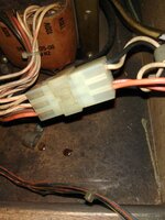
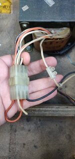
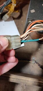
Problem is, the white/orange wire is going to pin 7, and it’s the other end of that that is snipped. White/grey is going to - I presume - the line filter.So the snipped white wire, I think is just bi-passing the connector.
View attachment 100152
Easy to see in that picture. I'm trying to work out, what number the pins are in the plug.")
Pinball info
You are using an out of date browser. It may not display this or other websites correctly.
You should upgrade or use an alternative browser.
You should upgrade or use an alternative browser.
WPC(89) transformer wiring anomaly
- Thread starter Durzel
- Start date

Are you sure that’s right @myPinballs ?
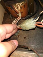
The rear of his plug matches your instructions..
View attachment 100151
(I don’t think @biglouieuk is holding it up right in the last photo, there’s no configuration that has the orange loop use pin 1)
Happy to be told I’m wrong.
Yes, i'm talking about returning the snipped wires back to the correct settings. His problem is more complex than just looking at the picture in my instructions as its been hacked and thats just for use when nothings been messed about with, to connect the new power supply.
The white line input feed on his game is currently directly connected to the white/brown wire instead of the white/orange (on the transformer plug side) which makes it a 218vac setting.
Yup.
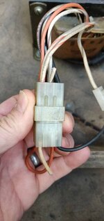
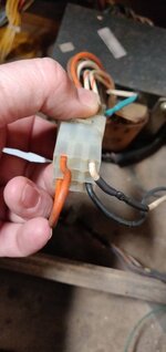
I need to work out what needs to go on the north side of the connector (that snipped wire needs reconnecting I believe)
But it goes.to nothing on the south side.of the connector..currently...
Am I concluding that it's a case of putting the snippet wires back to where they have been snipped from? I'll need to check if I have any crimp pins the right size..
Does that give me the 230v set up?
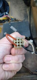
I cant work out the numbering of the pins in the connector to match up to the schematics yet!
Does that give me the 230v set up?
I cant work out the numbering of the pins in the connector to match up to the schematics yet!
Gotcha, see what you mean.Yes, i'm talking about returning the snipped wires back to the correct settings. His problem is more complex than just looking at the picture in my instructions as its been hacked and thats just for use when nothings been messed about with, to connect the new power supply.
The white line input feed on his game is currently directly connected to the white/brown wire instead of the white/orange (on the transformer plug side) which makes it a 218vac setting.
The white/orange wire coming out of the rear of the female connector is live. It may be permanently live because it’s the line filter that has the switch. That needs to connect to the wire that is currently going to the bit that’s spliced.Am I concluding that it's a case of putting the snippet wires back to where they have been snipped from? I'll need to check if I have any crimp pins the right size..
Does that give me the 230v set up?
I cant work out the numbering of the pins in the connector to match up to the schematics yet!
The white/grey wire that is currently spliced needs to be reconnected to the cut wire of the male connector. Technically you don’t need to do this because you only need this if you needed to change the voltage profile again.

Last edited:
Jesus is there anything that Andy actually did correctly on that pin I see he couldn’t be bothered to even sand the cab inside when he fitted the new decals
I can send you a pic of my tz which is correct if you want or just listen to Jim
I can send you a pic of my tz which is correct if you want or just listen to Jim
All help is appreciated, but as you say, I do what Jim tells me! Ha. But a picture of what good looks like would help me. I'm a visual type of person!Jesus is there anything that Andy actually did correctly on that pin I see he couldn’t be bothered to even sand the cab inside when he fitted the new decals
I can send you a pic of my tz which is correct if you want or just listen to Jim
New decals need to be ordered, they are peeling off top and bottom on both sides.
I will take pics when I am back home the numbers on the connector blocks are hard to see
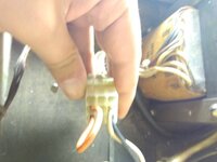
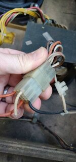
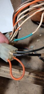
So if orange/white on the north side of the connector is perm live. Then that white cable hanging out of the back of the south connector is live mains voltage, just sitting there waiting for me to accidentally touch!?The white/orange wire coming out of the rear of the female connector is live. It may be permanently live because it’s the line filter that has the switch. That needs to connect to the wire that is currently going to the bit that’s spliced.
The white/grey wire that is currently spliced needs to be reconnected to the cut wire of the male connector. Technically you don’t need to do this because you only need this if you needed to change the voltage profile again.
View attachment 100161
Can't be.
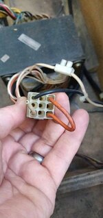
Pic of mine disregard the blue and brown wire as that is the my Pinball’s mod
I suspect the pin has got burned over time and someone has done a bodge on it to do it properly I doubt there is enough wire to be able to do that but you could do a nicer job
You wouldn’t expect a fully qualified electronic engineer to let this get by him
I suspect the pin has got burned over time and someone has done a bodge on it to do it properly I doubt there is enough wire to be able to do that but you could do a nicer job
You wouldn’t expect a fully qualified electronic engineer to let this get by him
Thanks for the pic. Helpful as I only found this because I am putting the @myPinballs power board mod in this machine and I sent him a.picture to check and he spotted it!
So I have spliced the wires, soldered and heat shrinked them on both sides of the connector.
It looks right for 230v now. I think.
Haven't tested it yet...
So I have spliced the wires, soldered and heat shrinked them on both sides of the connector.
It looks right for 230v now. I think.
Haven't tested it yet...
Attachments
Last edited:
I don’t feel qualified to say to be honest so will leave that to the experts like @CHRIS B PINBALLS and @myPinballsSo if orange/white on the north side of the connector is perm live. Then that white cable hanging out of the back of the south connector is live mains voltage, just sitting there waiting for me to accidentally touch!?
Can't be.
Looking at the schematics I think I might have it backwards, with the utility power going to the line filter box (that has the switch) with the output from that going to the transformer.
A little knowledge is a dangerous thing, and when it comes to electrics it’s even worse - so I’ll defer to the other guys.
Sorry you’ve had so much grief with this pin.
Sorry you’ve had so much grief with this pin.
I've learnt so much in such a short time. I should thank Andy for that perhaps. Maybe he will offer to give me a grand back! Haha.
Tested.
Flippers...
All ok on the power shot in test mode...but fail on the hold test for left and top. They don't move...
I'll dig into that today. Maybe I now need to test voltages for flippers..
Flippers...
All ok on the power shot in test mode...but fail on the hold test for left and top. They don't move...
I'll dig into that today. Maybe I now need to test voltages for flippers..
Last edited:
Bit delayed with my reply as I’ve had a family emergency this weekend.( My step son ended up in hospital with tonsillitis so had to rush down to London to make sure he was ok. On the mend now!)Thanks for the pic. Helpful as I only found this because I am putting the @myPinballs power board mod in this machine and I sent him a.picture to check and he spotted it!
So I have spliced the wires, soldered and heat shrinked them on both sides of the connector.
It looks right for 230v now. I think.
Haven't tested it yet...
Pics look ok for the ‘rewire’ Back to normal uk setup and you can connect the mod power board as per the instructions now
on the flipper hold front. In test sometimes the hold won’t activate like that unless you move /hold the flipper bat up alittle yourself. Hold coils are not powerful enough to flip they just hold the bat up
As said above, the flipper hold tests are to see if it will hold the flipper up once it’s in the upright position. It isn’t unusual for it not to be able to lift the actual bat from resting position (as it’s the low power winding)
You’ll probably notice that coils fire a little weaker than they did before, due to the fact they are no longer being overcharged. This is normal too. That may even be why you noticed the hold tests lifting the bat before and thought that it was now wrong.
You’ll probably notice that coils fire a little weaker than they did before, due to the fact they are no longer being overcharged. This is normal too. That may even be why you noticed the hold tests lifting the bat before and thought that it was now wrong.
Last edited:
This is amazing, the game now plays much better with less "punch"
I noticed at FlipOut the other night that the games seemed to have less powerful flippers and it felt more controlled and "gentlemanly"
Now my flippers are the same. the ball isn't flying up and hitting the glass and there seems to be just a little more time, it's not as hectic as it was, in a good way.
Thank you all for your help with this. The new motor has arrived. I'll do the @myPinballs (thanks for spotting this issue) power board next. Then motor. Then bottom target replacements, then the side decal blades.
pedroborges
Registered
how do i have to make the connection on the transformer plug to have 230 volts ?