Hi
So I recently bought one of @myPinballs's Mod Power Expander boards, and set about installing it in my TAF yesterday - but got stuck.
Essentially, the instructions for the mod show a different plug wiring configuration to what I have. Once I realised this I obviously aborted the install for fear of doing damage.
I have done some research and established the following..
Here is the WPC schematics for the male power plug, and the female plug configuration for 230 VAC:

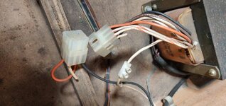
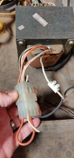
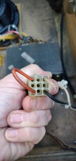
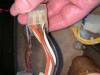
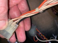
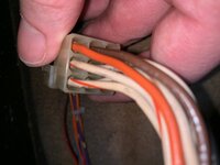
I have verified that the male portion of my transformer plug is correct per the above. The female part of the plug, however, is not wired the same as above. Mine looks like this:


So it looks to me like the white cable is plugged into pin 4 (white/brown on male) instead of pin 7 (white/orange), and my looped orange cable is in pin 3 (white/black) and pin 6 (brown) instead of pin 3 and pin 9 (orange) per the schematic.
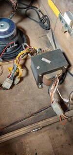
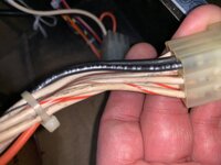
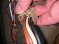
My line filter box looks like this - does this look normal?

What is confusing to me is that my game works perfectly in this configuration with no electrical issues that I am aware of or can see. I can repin the female connector if it is safe to do - i.e. move the white cable from pin 4 to pin 7, and one end of the orange loop from 6 to 9 - but not having electrical skills I don't know if this is a good idea or not. Because this configuration differs from what the schematics & @myPinballs's instructions show - I don't know where I'm supposed to insert the blue and brown cables from it.
What would be the consequences of repinning this the correct way? Is it possible the line filter box is wired "wrong" internally or something? Does anyone know the voltages each of these 9 wires from the transformer provide?
To confirm:
So I recently bought one of @myPinballs's Mod Power Expander boards, and set about installing it in my TAF yesterday - but got stuck.
Essentially, the instructions for the mod show a different plug wiring configuration to what I have. Once I realised this I obviously aborted the install for fear of doing damage.
I have done some research and established the following..
Here is the WPC schematics for the male power plug, and the female plug configuration for 230 VAC:
I have verified that the male portion of my transformer plug is correct per the above. The female part of the plug, however, is not wired the same as above. Mine looks like this:
So it looks to me like the white cable is plugged into pin 4 (white/brown on male) instead of pin 7 (white/orange), and my looped orange cable is in pin 3 (white/black) and pin 6 (brown) instead of pin 3 and pin 9 (orange) per the schematic.
My line filter box looks like this - does this look normal?
What is confusing to me is that my game works perfectly in this configuration with no electrical issues that I am aware of or can see. I can repin the female connector if it is safe to do - i.e. move the white cable from pin 4 to pin 7, and one end of the orange loop from 6 to 9 - but not having electrical skills I don't know if this is a good idea or not. Because this configuration differs from what the schematics & @myPinballs's instructions show - I don't know where I'm supposed to insert the blue and brown cables from it.
What would be the consequences of repinning this the correct way? Is it possible the line filter box is wired "wrong" internally or something? Does anyone know the voltages each of these 9 wires from the transformer provide?
To confirm:
- The game works 100% (except for a sticking flipper which is mechanical)
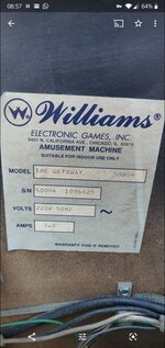
- It was sourced from Europe (Italy), and still has the Euro plug on it (plugged into an adaptor)
- I have the correct transformer - 5610-12835-00
- The male plug off the transformer is wired correctly per the WPC schematic
- Two pins (white, and one orange end of loop) on the female plug off the transformer are wired incorrectly - does not correspond to any voltage selection wiring configuration in the schematic
Attachments
Last edited:
")