Pinball info
You are using an out of date browser. It may not display this or other websites correctly.
You should upgrade or use an alternative browser.
You should upgrade or use an alternative browser.
In Progress The Shadow
- Thread starter SpiderPin
- Start date
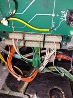
Loose orange green goes in j206-3
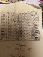
What I normally do is print out the switch matrix and in switch edges test work through each switch activating each swotch by hand and mark on the matrix
1 which switches dont acrivate at all with a cross
2. Which switches activate correstly and do not acrivate any other switches and
3. Which switches also acrivate other switches at the same time and if they do take note of the switch number they activate.
It them helps to work out where to look for the faults.
Your pic of the dmd in switch edges test tells us that switches 61 to 67 are acrivated and 85 to 88 are acrivated. If you look on the switch matrix all the opto switches are greyed out. If you have no balls in the ball trough then the image above should show all the opto switches activated and none of the others. So 85 to 88 is as it should be but 61 to 67 should be off. But 41 to 47 are optos and they should be activated so it looks like you may have some incorrect cross over between the circuit on column 4 and column 6.
Good start is to remove all column and row plugs, switch machine on, go into switch test and connect first row pin with all column pins and on to second row and so forth. All switches should register as single switches. By doing this you know that the CPU is OK. You can then start probing as per @Asiapinball's post.
If you get stuck on any bits I have just completed a full shop on one of these and have over 400 photos.Hi all, welcome to my first shop log, The Shadow.
I'm setting this up here as a placeholder until I can start work on the machine...
So we purchased the Shadow that was listed on here with no backbox boards, which appeared to be the only large missing parts along with a diverter, the phurba daggers, Mongol figures and some of the rings. I've managed to source the following:
- Entire backbox worth of boards + ribbon cables (Sprung for a Pinsound here!)
- New rubbers set
- Aurich translite (Very thankful for sourcing one of these!)
- Diverter + 2 new decals
- Replacement battlefield kicker + decals
- Phurba daggers
- Wall target
- New plastics set
- Custom coloured flasher caps
I believe that this should be everything to get TS functional - if that's the case, I'm moving on to the making it beautiful stage. I want to powder coat it (I'm thinking candy purple), get one of Stumblors wonderful XL colour DMD's and fully LED it. I've also seen the T2 restoration and am incredibly jealous of the chroming - I'm considering getting the ramps and wire forms re-polished / chromed / nickel plated but that's a bridge to cross once the machine plays.
Now, the cosmetic issues - there is some chipping on the cabinet. As far as this goes, the majority is in the black section of the artwork, so I think I may just follow the brilliant Elvira cabinet restores footsteps and use an airbrush to paint it after filling and sanding as opposed to re-decalling. As with all Shadow's, the Sanctum is pretty beat up, so I'm going to use an epoxy pen, sand and use a decal that Sven sent to me (Thank you!). Finally - it's missing the pistol shooter. These are unobtanium, so I'm looking at getting a custom plastic made to cover the area and make it a little more interesting while adding a button for the ball serve like Indy 500.
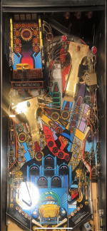
I've attached a photo of the state it's in currently. I can't wait to get started - if anyone has any tips, let me know!
View attachment 161189
Cheers
Kev
Having a hard time visualising this (on my account!) - how am I connecting the pins?Good start is to remove all column and row plugs, switch machine on, go into switch test and connect first row pin with all column pins and on to second row and so forth. All switches should register as single switches. By doing this you know that the CPU is OK. You can then start probing as per @Asiapinball's post.
Having a hard time visualising this (on my account!) - how am I connecting the pins?
(Since posting originally, II made a few small edits to the below for clarity)
In its simplest form you need a piece of wire (ideally white) a diode 1N400X (I usually use 1N4004) and a piece of heat shrink tube (ideally green).
Solder the non banded end of the diode to the wire (bottom wire in the pic) and then put the heat shrink wire over the diode and solder (top wire in the pic). You now have a switch, just the same as is under the playfield, with correct colour coded wires.
Disconnect J206, J207, J208 and J209 and go into switch edges test.
Now hold the white end of the wire against J209-1 pin on CPU board carefully avoiding touching any other pins. At the same time, hold the green (diode) end of the wire against J207-1 pin on the CPU board and then switch 11 should activate in switch edges test. Them move on to pin J207-2, then J207- 3 to J207-9 when you have tested all row 1 switches. Then move white end of the wire to pin J209-2 for the 2nd row and repeat what you did on first row and so on until all are tested.
It's quite fiddly to do in the machine and be very careful not to touch the DMD connector as there are high voltages there that can kill. Help of a second person to look at the screen and mark which switches are and are not working on the matirx is a bonus!
Would you like me to post you the test wire?
Paul

Last edited:
Actually, if you have J206, J207, J209 and J209 disconnected you don't need the diode in the wire to test the CPU board on its own - you can just use a wire without the diode. I use the wire with the diode to test if a playfield switch is the issue or not (amongst other things) so usually just use same when testing CPU switch matrix.
Thanks! That makes it very clear. Thanks for the offer but going to solder the parts tomorrow as will be leaving again next week so trying to do as much as possible!(Since posting originally, II made a few small edits to the below for clarity)
In its simplest form you need a piece of wire (ideally white) a diode 1N400X (I usually use 1N4004) and a piece of heat shrink tube (ideally green).
Solder the non banded end of the diode to the wire (bottom wire in the pic) and then put the heat shrink wire over the diode and solder (top wire in the pic). You now have a switch, just the same as is under the playfield, with correct colour coded wires.
Disconnect J206, J207, J208 and J209 and go into switch edges test.
Now hold the white end of the wire against J209-1 pin on CPU board carefully avoiding touching any other pins. At the same time, hold the green (diode) end of the wire against J207-1 pin on the CPU board and then switch 11 should activate in switch edges test. Them move on to pin J207-2, then J207- 3 to J207-9 when you have tested all row 1 switches. Then move white end of the wire to pin J209-2 for the 2nd row and repeat what you did on first row and so on until all are tested.
It's quite fiddly to do in the machine and be very careful not to touch the DMD connector as there are high voltages there that can kill. Help of a second person to look at the screen and mark which switches are and are not working on the matirx is a bonus!
Would you like me to post you the test wire?
Paul
View attachment 229270
As @Asiapinball said, you don’t need a diode, short piece of wire will suffice, no soldering required.
Guess who’s back?
A quick note to say I’d like to thank everyone who’s commented and helped so far. I wouldn’t be as far as I am without the help of this brilliant forum.
Before we get in to switches - an update. It’s been a while since I’ve updated the thread as I’ve been away but the topside has mostly gone back on now. Installed the new upper PF with the donor board and soldered everything in. Just need to install a few plastics and the diverters until what you’d see playing the game is pretty much done. As some of you may notice I decided to get the ramps and wire forms brass plated instead of the silver to lean in to the art deco theme - I’m a fan! With the amount of blood, sweat and (literal) tears that have gone in to this game I don’t think I could ever sell it so as long as I like it!
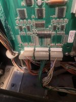
But what you don’t see when playing? Have been putting to work the tech knowledge from @drhex and @Asiapinball on the switch matrix and got an interesting result - alternate columns of switches are out. Odd. From my research it seems a U20 could do something like this, but the CPU is a brand new PinLED board so surely that’d be fine? Going to test the continuity on the chains next to see if I can find a break but the alternating makes me think it’s something else. Any ideas?
Side note - my J206 is missing the green and orange cable - how do you re-install the cable in to the header? If anyone has any expertise, let me know.
A quick note to say I’d like to thank everyone who’s commented and helped so far. I wouldn’t be as far as I am without the help of this brilliant forum.
Before we get in to switches - an update. It’s been a while since I’ve updated the thread as I’ve been away but the topside has mostly gone back on now. Installed the new upper PF with the donor board and soldered everything in. Just need to install a few plastics and the diverters until what you’d see playing the game is pretty much done. As some of you may notice I decided to get the ramps and wire forms brass plated instead of the silver to lean in to the art deco theme - I’m a fan! With the amount of blood, sweat and (literal) tears that have gone in to this game I don’t think I could ever sell it so as long as I like it!
But what you don’t see when playing? Have been putting to work the tech knowledge from @drhex and @Asiapinball on the switch matrix and got an interesting result - alternate columns of switches are out. Odd. From my research it seems a U20 could do something like this, but the CPU is a brand new PinLED board so surely that’d be fine? Going to test the continuity on the chains next to see if I can find a break but the alternating makes me think it’s something else. Any ideas?
Side note - my J206 is missing the green and orange cable - how do you re-install the cable in to the header? If anyone has any expertise, let me know.
Attachments
Continuity looks good to me but going to double check later.
Have been reading the response here (https://pinside.com/pinball/forum/topic/switch-column-not-working) and it mentions a column out could be caused by the opto boards. Some of mine look a bit… worse for wear so I wonder if this could be the cause.
U20 is still stuck in my mind but I figure with the board being a new repro it’s unlikely.
Double checked U20 was on properly and it was. 12v leds also seem to be on on the boards and I think I’ve tested the 12V before. Sort of at a loss at this point for where to go next… found an online repair guide that I’ll follow but sort of stumped by this.
I figure multiple whole columns being out also points away from a continuity issue?
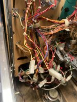
Side note - anyone with a Shadow or anyone with photos are you able to tell me where these cables go? Think they’re for the rings but I’m missing a few pages of my manual so can’t check. Back corner of the PF.
I figure multiple whole columns being out also points away from a continuity issue?
Side note - anyone with a Shadow or anyone with photos are you able to tell me where these cables go? Think they’re for the rings but I’m missing a few pages of my manual so can’t check. Back corner of the PF.
Attachments
Last edited:
So - can't find continuity on the failed switch rows at any switch (as I expected). I've looked from the board to the first switch but there's no obvious breakage. U20 is good. Was looking at checking U23 but I haven't worked out how to do that just yet.
I'm wondering if the next step is buying a new CPU board, but in all honesty I could do without the expense!
The only other thing I could think - would it be possible for this to be caused by a bad underside PF opto board?
I'm wondering if the next step is buying a new CPU board, but in all honesty I could do without the expense!
The only other thing I could think - would it be possible for this to be caused by a bad underside PF opto board?
Tested all my coils and all have a minimum of 3 ohms. Some over a hundred (which is normal, isn’t it?). So I don’t think coils are my issue.
Fuses F103 and F104 keep blowing which I understand to generally be due to coil issues but they also control flashers - I think this has got to be the issue (or a wiring short somewhere? Nothing obvious mind) as my coils seem good. Back to the drawing board!
Fuses F103 and F104 keep blowing which I understand to generally be due to coil issues but they also control flashers - I think this has got to be the issue (or a wiring short somewhere? Nothing obvious mind) as my coils seem good. Back to the drawing board!