What's new
Pinball info

Register a free account today to become a member! Once signed in, you'll be able to participate on this site by adding your own topics and posts, as well as connect with other members through your own private inbox!

The New No Fear Help Thread

The magnet will probably be fine. The cpu knows the switch is stuck so won’t energise the magnet. It’s been a while since I worked on this area but start like this.

Locate the opto emitter. It’s the white t-shaped plastic with small LED pcb mounted on it. Measure the voltage across it. If 12volts the led is broken and needs to be replaced. An led pcb is £3.50. If the reading is 0volts you have no power to this opto and you need to find out where it’s gone. If the reading is approx 0.7volts then the led is assumed fine so you have to proceed to examine the receiver.
 
Thanks @pinballmania - I might try and get to this tonight, order up the parts for the weekend, I have Saturday to myself :)
 
F57F1E2C-FEEE-49DC-8B12-69D561E11498.jpeg

Success!!! Cleaned the opto with a cotton bud and some isopropanol alcohol and the dried it off, thing was absolutely filthy - that cleared up the switch issue and as @Courtney Blush and @pinballmania rightly said, the magnet issue too. So switch faults are now cleared, will order new coil tonight and some new rubbers to solve the popper issue and hopefully with the parts for the flasher issue on the board, be error free!!
 
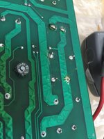
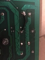
So the cap an BR had been replaced previously, apparently... poorly according to the person who helped me, which can be seen by the badly soldered leg on the capacitor (pictured), when checked the cap reading comparative to the new one was much lower, .5 compared to 3.8 - so hopefully this is going to resolve the issue, although, one has to question if this is cause or effect, given a previous replacement...

FB0500B3-6260-4462-AA00-549369F51D85.jpeg
 
So.....

Fuse not blowing, but flashers not either... LED not lit, but only just in so didnt get to test tp...any other ideas?
 
Did your guy check continuity between the newly installed capacitor and the bridge? The tracks to the cap run under the capacitor and a connection is difficult where the track is under the cap. There should be through hole plating but it’s usually removed when the cap is pulled out. If there’s lack of continuity then you’ll have to add a wire link to replace the track.
The bridge has one pin offset, this is positive and should link to the pos side of the capacitor. The diagonally opposite pin is -ve and should connect to the - side of the capacitor.
 
Exactly what I was going to say.

Also... Meter the fuse itself out of circuit, could be a faulty fuse, I have had it happen.

Did your guy check continuity between the newly installed capacitor and the bridge? The tracks to the cap run under the capacitor and a connection is difficult where the track is under the cap. There should be through hole plating but it’s usually removed when the cap is pulled out. If there’s lack of continuity then you’ll have to add a wire link to replace the track.
The bridge has one pin offset, this is positive and should link to the pos side of the capacitor. The diagonally opposite pin is -ve and should connect to the - side of the capacitor.
 
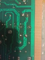
That's some terrible soldering, I'd reflow the whole lot on that board.

What the hell is that big blob at all?
 
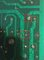
Thanks all again, offset pin (positive) to cap positive showing continuity, negative on BR not showing continuity to negative on cap, which was the one pictured before with the solder raising off of the board. I’ll tin up a jumper tonight which I have done before and run it through.

As I’m looking at this image it’s the left capacitor solder and the top left BR pin.

(Bottom right BR pin to right hand cap pin are getting continuity)

image.jpg
 
Ok - just to clarify, continuity between the green highlighted ones, the red ones, no continuity and should have it, I will add the green line as a jumper wire.

In terms of wire thickness, I have some really thin stuff I used for a board repair on Laser Ball, or some 16 AWG stuff I used for a BR fusing on that machine too, does the wire type matter for this application?

12.png
 
It’s only a short run, so resistance is less of an issue, but based on the width of the incoming track to the top square (gnd I assume), compared to other smaller tracks on that board, I would want to use something at least the same gauge as the wires coming off the board, just to be on the safe side.

Definitely worth taking arvs advice and tidying up any shonky soldering while you are at it.

Great job so far [emoji106]
 
Cheers, this seems to be the only work done to this board, I think the engineer at work has done a reasonable job with the bits he has done, I will ensure I do my best not to ruin that tonight.
 
Great thread - thanks for documenting it so thoroughly! And great work on figuring it all out with everyone. Although not ideal, I bet you know loads about the machine now and will feel way more confident with any small issues that pop up in the future.
 
HI all,

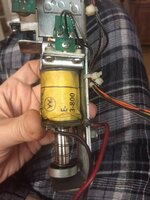
Got the new coil from @pinballmania - really speedy service on top of all the help. Just about to swap this over and the old coil has no diode on it, I have some I bought for LB 1N4007 I think. Should I fit one with the band to positive (red) on this or is it ok as is?

image.jpg
 
Hi, James,

There isn't really a need for adding a diode to the coil, the Wpc system has the tie-back diodes on the driver board(s); even though the flipper coils still have diodes, so does the FlipTronic II pcb
 
Last edited:
Yep - had it up and running sans diode, still getting a kickback on important game modes... :(
 
Can you take the mountain plastic off so we can see what’s happening under the mountain. I can’t remember what the popper exit looks like but you might be able to put a slight bend into it so that the ball is directed to a different point so that any bounce back doesn’t direct it back into the popper.
 
Hi all,

Please do to report after Andy’s delivery (@pinballmania) that the machine is now 100% fault free.

Firstly, when the machine arrived the two back legs had different size adjustment feet so I could only get the game between the first line, not the recommended second line. Managed to get the leg off that had the sorter one, using a bench as a support, change this foot over and then get it back on and adjust up, all levels horizontal and vertically if you will in spec (which helps, but doesn’t irradicate a left ramp drain if you don’t hit it with pace, the point I guess)

Next was on to this popper, bloomin’ popper, Andy’s suggestion of the weaker coil along with @Courtney Blush suggesting some adjustments were the trick, the weaker coil certainly takes the sting out but I was still getting some kickback, beings I had the chance, I’ll explain why in a second, I’ve put two metal packing shims in the scoop which have aligned it now, just played for an hour I would say, 0 bouncbacks.

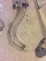
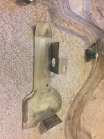
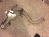
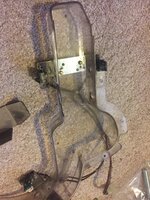
Lastly, I ordered up some yellow post protectors, the flippers are yellow and as a NCFC fan, this to me was a great win. So I’ve been busy putting those on. Half way through this, under the skull posts, I drop one down the subway... so.. subway has to come off, it needed a good clean anyway :/

DF653140-DC68-407E-8815-6604BC387F37.jpeg

4FDB16A4-9DF6-4A6C-B896-15C58F320AE7.jpeg

And after

701179F3-BA8B-4C1A-9B40-BC8BA7BBF3A9.jpeg

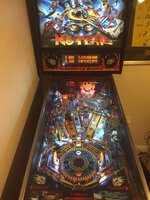
So posts on, ensuring nothing else could fall into that blooming subway, subway on, solenoid back in. The game was good to go.

09124A7D-2539-4B38-99F7-6D5DAD671806.jpeg

I’ll buy a DMD Xpress once they come out to sort that line out... did @DrPinball day that yellow was an option :p
 

Attachments

  • 7F8EE932-2438-44A7-BEA8-46B943DC926C.jpeg
    7F8EE932-2438-44A7-BEA8-46B943DC926C.jpeg
    126.8 KB · Views: 10
Sure it’s only temporary but hey, what do ya know!

image.jpg
 
Back
Top Bottom