What's new
Pinball info

Register a free account today to become a member! Once signed in, you'll be able to participate on this site by adding your own topics and posts, as well as connect with other members through your own private inbox!

The New No Fear Help Thread

James

Site Supporter
Joined
Dec 29, 2017
Messages
5,101
Location
Norwich
Alias
James
Hi all,

I have left it with Steve that I would like some tech support, that's in his area and I understand he has contacted John Wyatt to get some for me, while he awaits a response, I am going to crack on diagnosing and look to minimize that cost. Let's leave it as it is with that side of things for this thread. I have requested the previous thread be removed, in a hope for the right thing to occur, in whatever form that may take.


Popper:

So, first issue I think is alignment on the right and side popper, I am unsure if everyone remembers but after hitting the center skull shot, (or any subway shot) the popper can either return with such ferocity it pings back and pops again, or this little gem happens. I am guessing this is just a case of jimmying the arm around until the issue disappears?


image1.jpeg

Flashers

None of the flashers in the game work, I started by removing F111 which had a .250 in it instead of the 5A SB required, plugged in a new fuse and it blew instantly. I then tried removing both J107-6 and J107-5 independently of each other and refused, to see whether the pull was coming from either the play field, or the backbox, unfortunately, both blew the fuse once more. I then fused with connections and blew again.

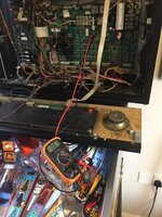
Looking at the schematic, the bridge rectifier BR4 feeds this the R224 resistor, which is reading 1.3 on the multi meter, set at 200. I have moved the multi meter to test point Test Point 7 and review if I am getting 20 vaults, I think I have set my meter correctly here, with the red croc clip on the top and am getting and grounding to the braid. I tried the same at the fuse connections and am getting -.14 with meter set at 20V, trying again with the flasher test running, getting the same at TP and fuse.

What I don't get if I am getting nothing across there voltage wise, why would the fuse blow...

Thank you for any help, once I get these two sorted, it will be onto the upper left magnet and opto issue.
 

Attachments

  • image1 (2).jpeg
    image1 (2).jpeg
    130 KB · Views: 21
Last edited:
The fuse is on the input side. The bridge is short circuit so blows the fuse. You won’t get any volts because the fuse is blown.

It’s a powerful coil on the vuk. It’s correct as per design but often poppers are too powerful. You can change the coil to a weaker one eg 25-1000. This is commonly done on Star Trek Next Gen where the poppers are so strong the balls jump out of the canons, and also a cure in Whitewater where the left kick out sends it straight down the middle school. It’s not really a fault, just annoying.
 
If you’re looking for volts at the input side, then your meter needs to be set on an AC scale.
 
Ahhh Andy and his wise, wise words of wisdom. Heed his teachings for they are gospel. :thumbs:
 
If you’re looking for volts at the input side, then your meter needs to be set on an AC scale.

Hi Andy, thank you for the advice, if I bridge over the fuse connector, what voltage AC should I get, this won't be on the schematic anywhere I don't assume? Obviously, I want to check this first. Although if I am reading this right, it seems you are sure that BR4 is the cause of the short...

Thanks for the input :)
 
Well. Haven’t ever done that measurement. But in theory if the bridge IS short you will see something like 20-30v AC i guess. If the bridge is not short then there should be close zero volts AC
 
You are doing a stalla job so far mate
Listen to Andy his advice is spot on and he explains things so well much better than I can
As Andy said with what you have done so far it’s more than likely the bridge rectifier rather then mess about I normally just cut them off replace the fuse and see if it blows again I bet it won’t problem sorted cheap to buy easy to fit too in fact a good board repair to start on for a newbie the fuses are always 250v so that was correct to start with
 
Re the ball poper if you have a manual then check it’s built up the way it should be failing that I think it more than likely adjustment and a bit of tinkering
 
There is a block of wood often glued to the plastic under the wireframe to stop it shooting back into the popper. When mine snapped off, I got this problem too.

It only happens 1 in 20, but I was thinking of changing the cool as a more permanent solution as per Andy’s suggestion.
 
I’m going to check 16VAC at J102 pins 1,2 and 3,4 (from pinside) if I get 16VAC there I can be sure it’s the BR popping the fuse right? Hopefully my local maplin has one in tomorrow if needed. I’ve done some soldering recently on a Williams System 4, but don’t want to F this board up, although around the BR it looks fairly spacious. I read something about thermal paste though, is that needed too?
 
I’m going to check 16VAC at J102 pins 1,2 and 3,4 (from pinside) if I get 16VAC there I can be sure it’s the BR popping the fuse right? Hopefully my local maplin has one in tomorrow if needed. I’ve done some soldering recently on a Williams System 4, but don’t want to F this board up, although around the BR it looks fairly spacious. I read something about thermal paste though, is that needed too?
Thermal paste between the BR and the heat sink - if it has one. I'm not sure if it's absolutely *essential* but Maplins will have it and it's cheap as chips so may as well.

Sent from my D5833 using Tapatalk
 
Maplin only sell the lug type. You need a wire one. I normally have them but am out of stock. If you take the board out you can test the bridge with your meter. Put it on a diode setting and measure between adjacent pins. Repeat by swapping the probes on each pair. In one direction you’ll get no reading in the other you’ll get a voltage reading of around 0.5-0.7v. If the bridge is short one of the pairs will give you a zero reading in both directions.
 
Thabks @pinballmania - any idea when you’ll get some in? I will test the BR in a moment, got some post tubers that are looking a little worn as well as some cleaning chemical and the lower rated coil I’ll pop on.. might order the others without the BR if it’ll be a while.
 
CE02D0F8-0FA2-43D0-9EDB-1BE43F05DD6F.jpeg I couldn’t get at the bottom legs very easily so I made myself this little beauty, getting 1 on the multi meter one way and a readin of 451 the other, which sounds within spec...

Just out of curiosity - found this in the cab... normally wires aren’t left off so thought maybe this has something to do with the issues.

54E7704D-EA18-403E-A783-9B0039B707DE.jpeg
 
Oh... No just left to right, left to right... so two pairs I have to go round all four do I...
 
Yep. That’s why I said adjacent pairs. A bridge has four sections internally between each pair of wires around the outside. If any one has gone short then there’s a problem.
 
Aha - I will give that a look see tomorrow, any idea on the stock arriving? I can wait as the game plays without flahsers, just be nice to have no faults.
 
Ok so this is weird, i have tested the BR and have got the below readings, which all seem within spec, so I moved on to the connectors mentioned previously.

Screen Shot 2018-02-03 at 20.07.18.png
So at J102, I tried to test between pin 1/2 then 3/4 which I checked with a continuity test, the line beeped, so I assume that this is a connection, yet, when I switch the game on, I get no AC off of the multi-meter. I cannot understand this though, because if this isn't bringing anything in, how can the fuse be popping?
 
ok, do you have the correct input voltage at the live side of the fuse (AC). remove the BR and re-fuse and measure the input to the BR, make sure it's correct. Measure your BR with the meter on diode test and check forward and reverse readings.
 
The BR is testing as above and 1 in other direction, the AC side I am getting nothing on the multi meter, which baffles me as if there is no AC, how is the fuse blowing?

I checked a continuity test on the plug I am checking for AC and it is beeping... but machine powered on, nothing.
 
In the bottom right of your picture the wiring loom looks very black. Is this just bad lighting or is there any overheating of the wires there?
 
Have you measured some other AC voltages to ensure your meter is working correctly on AC?
 
When you measure for AC the probes should both be on pins 1 and 2. Not one probe on Ground like when you measure DC.
 
Have you measured some other AC voltages to ensure your meter is working correctly on AC?

Yep did the same test, checked this off on a LB that I have - circuit gets continuity as the NF one does, but the correct VAC is coming through on the meter...

6A3FBB82-0AB1-473C-A0B8-3B490591CF00.jpeg
 
Last edited:
When you measure for AC the probes should both be on pins 1 and 2. Not one probe on Ground like when you measure DC.

Yes pin one and two on the actual plug, not the board, checked this is a circuit with a continuity test...
 
Back
Top Bottom