What's new
Pinball info

Register a free account today to become a member! Once signed in, you'll be able to participate on this site by adding your own topics and posts, as well as connect with other members through your own private inbox!

T2 - small snags

Dinsdale

Site Supporter
Joined
Oct 19, 2022
Messages
318
Location
UK
Hey guys

So, some of you who followed my other thread about getting my machine up the stairs know that I had to disconnect the backbox to do this. As a result, I was open to the fact that one or two snags may become apparent.

So I've spent the last day and a half playing the game and have noticed some small snags.

1. Boot test showing "Check Switch 12 - Left Flipper"

When I book the game, it tells me to press enter. When I do, it displays "Check Switch 12 - Left Flipper". The left flipper seemingly works fine, but I wanted to play it a bit more to see if any issues arose.

Well, on T2's video mode, you use the flippers to control the target on the DMD. When I press the right one, the target moves to the right. However, when I pressed the left, the flipper moved, but the target didn't.

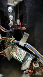
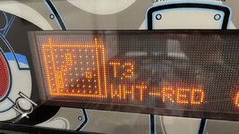
Any ideas on how to fix and clear this error? I did look on the specific switch in the Test and it's pointing to something. I've pictured this.


2. Can't change default high scores

I wanted to clear or amend the high scores of the default "Grand Champion" and "Top Marksmen" scores to something realistically beatable so friends and family could enter theirs.

I Google'd and saw that this was simple from a thread on Pinside, but while my choices do save and are in the adjustments menu, they don't actually reflect that on the game when I put it back into attract mode.

I adjusted A.4-10, A.4-11, A.4-12, A.4-13.

Any ideas how I can get this to stick? Am I doing something wrong?

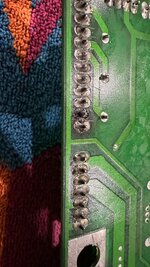
3. One lamp is not lighting up

I did lamp tests and all but one isn't showing up. I don't think that's too bad for a first go at putting stuff back together. I did notice one black wire was loose when I put it back together so that could be it. If it helps, it's the "Load for Jackpot" lamp. It says "RED-GRY YEL-RES"

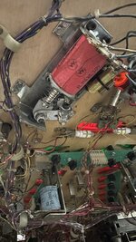
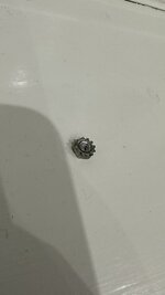
4. Random nut popped off

A random but popped off when a ball hit the apron area. I couldn't immediately see where from. I have pictured this. Any idea where it should go? I've had a look and there is nowhere immediately obviously, but it does look slightly different from the other nuts I see.

Thanks in advance, I'm still under the learning tree but I do find it fascinating how this old tech worked so well!
 

Attachments

  • 617283FE-D1F3-4935-A985-428B6FDF3396.jpeg
    617283FE-D1F3-4935-A985-428B6FDF3396.jpeg
    135 KB · Views: 12
  • 689339C4-0654-4499-8805-DE8BE54EBDC5.jpeg
    689339C4-0654-4499-8805-DE8BE54EBDC5.jpeg
    27.8 KB · Views: 12
A quickie on the high scores.

Once you've set new defaults you need to go into Utilities and "Reset H.S.T.D".
Then it'll reset everything to the set defaults.

The left flipper issue might be a leaf switch on the left flipper button that's used for lane change and video mode. Just have a look at the button inside the cabinet with the playfield up and you should be able to see if there's another leaf switch that isn't making contact. Fairly simple to adjust.

Just guessing mind, it works like that on other games so it might be a solution for you.
 
@David_Vi has you covered on 1&2. Check both leaf switches get activated.

Bulbs blow if incandescent, LED’s are longer living. Can you swap in a know working bulb to rule that out?
Do you have a multimeter and soldering iron?
I would get the manual out, work out what wires power that bulb and trace with the multimeter if it is connected. There is a matrix that shows what else it is connected to in series and in parallel.

Nuts do loosen in movement but also under the intense environment of a flying silver ball. That nut is pretty generic on these machines, so you need to go hunting what it loose.

All these things are normal in pin ownership so welcome to the club. ;)
 
Hi score is sorted, thanks!

This is the leaf spring, right? It looks ok but I am not exactly experienced enough to confirm or deny that.

I do have a soldering iron. Not a multi meter. I'm less concerned about the light at this stage, it is an LED though. @ChrisFormela did a wonderful job LED'ing everything. I really think something is loose. I'll open the backbox and take a look.
 

Attachments

  • 552F36A7-C57E-44BA-9126-80D99AEA6DA0.jpeg
    552F36A7-C57E-44BA-9126-80D99AEA6DA0.jpeg
    91.5 KB · Views: 24
Leaf spring switch is the one right next to the flipper coil on the flipper mec !
That pic is unclear to me but it looks like it’s the flipper switch on the side of the cabinet ?
bulbs can go or it could be a bad connection in bulb holder !

Congratulations taking the head off and on again !!
My first pin it took me about a month before I was able to take the glass off 😂
 
Is it not the side of the cabinet I need to be looking at? I'm totally new to this. Here's a pic of what I think is the flipper mechanism on the underside of the playfield.
 

Attachments

  • 9FAFE906-CB5C-42B1-8572-08B6F37D67A8.jpeg
    9FAFE906-CB5C-42B1-8572-08B6F37D67A8.jpeg
    117.3 KB · Views: 24
That’s the one . When the flipper is energised , the flipper plunger moves and the switch contact opens or does it close, I always gets that mixed up . The coil has a high and low voltage. High for a flip and low for a hold . Look at the over flipper for comparison .
 
Correct me if I am wrong but I am pretty sure on this board set the flipper lane change switches are actually done via an opto chip which detects the flipper voltage and is connected to the switch matrix, there is a left/right one. If flipper works but lane switch does not, it might be a bad opto chip.
 
This is a pic from ipdb1162A13A-22FA-4446-9830-C8DEF5E4CFCE.png
So contacts should be closed then open and it looks like you have the weaker coil on too !
 
Correct me if I am wrong but I am pretty sure on this board set the flipper lane change switches are actually done via an opto chip which detects the flipper voltage and is connected to the switch matrix, there is a left/right one. If flipper works but lane switch does not, it might be a bad opto chip.
It's pre fliptronics so older style switches and not optos.
 
@Dinsdale first step would be to check the wires at j208 and j209 on cpu board for any loose wires and reseat any ribbon cable you took off as most likely fault introduced when you disconnected. The link I sent describes continuity issues on the boards but you may have continuity issues at the connectors.
 
Thanks for all the help and pointing to threads etc. That guy has the exact same symptoms as I had - even entering the name for the scores. I had to toggle right across using the right flipper and couldn't go back. I thought "that's bad design" but actually it makes sense as it is relying on the same function as going left on video mode.

Anyway, there is nothing plugged into J208 and there wasn't on my pre-strip down video/photos. J209 has the something, so I've disconnected and reconnected it.

Reseated all ribbon cables to that board too.

Still getting the same error regarding switch but we do have some good news.

All lamps are now lit on the lamp test. So reseating did something.

EDIT: One of the check point lamps isn't working. I'm getting there.

EDIT 2: Now check point lamp seems intermittent. Jackpot lamp gone again.

I've done the flasher test and some are flashing on the backglass such as "right sling". Can fix that later, I may have something plugged into the wrong place.
 
Last edited:
To clarify re. Lane Change/Status Report/Initial Entry 'contacts', T2 will have a tiny opto-coupler chip for each flipper, close to the flipper relay on the Power/Driver board. Williams dispensed with additional switches on the flippers themselves* during the System 11 era (the flyer for Jokerz! mentions "Solid-State Lane Change"). The flipper power switches the opto chip, via a large resistor.

* though a couple of games, Swords of Fury and Taxi, have micro-switches tagged onto the flipper buttons, rather than a leaf switch spurred from the flipper End of Stroke switch
 
Last edited:
To clarify re. Lane Change/Status Report/Initial Entry 'contacts', T2 will have a tiny opto-coupler chip for each flipper, close to the flipper relay on the Power/Driver board.
Yes! I bought a multimeter and tested them as best I could with the board still in the back box.

One chip gives a reading of 1800-1900 on one side, nothing on the other (my understand is that this means it's good).

The other gave no reading at all, which may mean that's the culprit.
 
Looking at your picture of the display showing T.3, the 'Single Switch' section; the grid shows switches closed as 1,5/1,6/1,7 (the three storage trough switches), 2,4 which is wired permanently closed as proof that the switch matrix 12v is good, 3,2 & 3,3 the Gun Mark and Home switches, and 6,5 'Low Chase Loop', a rollover wire switch which shouldn't be showing unless you were closing it at the time. It's the lower of the two switches in the top right corner, there are two in order to show which way a ball is moving through the Chase Loop channel.

Single Switch is handy to check on any one switch; only the switch selected will show its name, colours, etc in text on the display. Though Bride of Pinbot didn't have a dot matrix, the Single Switch option of the Wpc board set was useful with a non-working skill shot switch; in a lane of five closely-placed switches, quite inaccessible by hand, selecting Skill Shot 200K and dropping the ball into the lane showed that it didn't register. The other switch tests would've been less helpful - Levels would only have shown if it was stuck Closed, and Edges would've shown all five switches (or not) in rapid succession as the ball passed over them.
 
Last edited:
Looking at your picture of the display showing T.3, the 'Single Switch' section; the grid shows switches closed as 1,5/1,6/1,7 (the three storage trough switches), 2,4 which is wired permanently closed as proof that the switch matrix 12v is good, 3,2 & 3,3 the Gun Mark and Home switches, and 6,5 'Low Chase Loop' a rollover wire switch which shouldn't be showing unless you were closing it at the time. It's the lower of the two switches in the top right corner, there are two in order to show which way a ball is moving through the Chase Loop channel.

Single Switch is handy to check on any one switch; only the switch selected will show its name, colours, etc in text on the display. Though Bride of Pinbot didn't have a dot matrix, the Single Switch option of the Wpc board set was useful with a non-working skill shot switch; in a lane of five closely-placed switches, quite inaccessible by hand, selecting Skill Shot 200K and dropping the ball into the lane showed that it didn't register. The other switch tests would've been less helpful - Levels would only have shown if it was stuck Closed, and Edges would've shown all five switches (or not) in rapid succession as the ball passed over them.
Thanks. I'm due to get my soldering iron tomorrow so I can (attempt) to change the 4N25.

Am I right in thinking that from your post; that may not be the only cause? What do you suggest I do about those other switches being closed/open?

Do I need to clarify my test? Happy to video it if need be?
 
I don't think it's connected to the flipper switch, I was simply remarking on the indications shown on the display picture; a box outline on the grid denotes a closed switch, and my curiosity in looking at the paperwork for T2 revealed what they were. The trough switches and gun I'd expect, and the test 'switch' is a given (without it, the machine wouldn't go into attract mode, but lock up and display an error message). The one I was concerned with was 6,5, the lower Chase Loop rollover. Normally that should only close briefly, as a ball passes through the channel; the order in which the two switches close shows which way it's moving.

I've since looked at the schematic for the Power/Driver board, which shows that the switch lines for the flippers, Column 1 and Rows 1 & 2, are fed back to the Cpu board via the ribbon cable. These are known for problems, but I should think that the seller would've made sure about it, and in any case you may have detached and re-connected it yourself. If you feel like risking it, the chips have Column 1 connected to pin 4, and their Row connected to pin 5, so shorting those pins of U7 should see a left switch indication.

What sort of iron are you planning to use? I wouldn't risk more than 25 or 30 Watts for circuit boards. In any case, I'd cut the pins of the chip first, and deal with each remnant separately.
 
Last edited:
I don't think it's connected to the flipper switch, I was simply remarking on the indications shown on the display picture; a box outline on the grid denotes a closed switch, and my curiosity in looking at the paperwork for T2 revealed what they were. The trough switches and gun I'd expect, and the test 'switch' is a given (without it, the machine wouldn't go into attract mode, but lock up and display an error message). The one I was concerned with was 6,5, the lower Chase Loop rollover. Normally that should only close briefly, as a ball passes through the channel; the order in which the two switches close shows which way it's moving.

I've since looked at the schematic for the Power/Driver board, which shows that the switch lines for the flippers, Column 1 and Rows 1 & 2, are fed back to the Cpu board via the ribbon cable. These are known for problems, but I should think that the seller would've made sure about it, and in any case you may have detached and re-connected it yourself. If you feel like risking it, the chips have Column 1 connected to pin 4, and their Row connected to pin 5, so shorting those pins of U7 should see a left switch indication.

What sort of iron are you planning to use? I wouldn't risk more than 25 or 30 Watts for circuit boards. In any case, I'd cut the pins of the chip first, and deal with each remnant separately.
I'm using this: Soldering Iron Kit 80W https://amzn.eu/d/9cAOuWy

I will try to reseat ribbon cables, unless you think I should just buy another set? I need to order some flipper rebuild kits from Pinball Heaven anyway as mine are really weak.

Can you also explain what "jumping" a switch is? Explain like I'm 5, how do I do it, what do I need? Sorry for the noob question.
 
Watch out, 80 W is more suited to soldering playfield coils, it's too much for circuit board traces and pads.

Re. the flippers of your game; someone's already mentioned that it has 'Red' 11630 coils. T2 was originally built with the more powerful 'Blue' 11629 coils, due to it having large ramps. Red was the standard issue for Williams games, with Blue being used where needed. T2 doesn't have solid-state 'fliptronic' control of the flipper coils, so it has high-current switches for End-of-Stroke on the flipper units, and for the cabinet buttons. Looking at the picture of your machine in entry No.6 above, the grey plastic linkage is the older 'pre-fliptronic' type, which is right for T2, with the conical compression spring. It looks alright, but the EoS switch doesn't look as good, and is critical for flipper power, so be sure to obtain a couple, and the yellow capacitors which are used to suppress the spark which attempts to jump across the contacts as the switch opens.

The imported picture in entry No.9 shows the Blue flipper coils, mounted as intended with the terminals away from the coil stop end. Though it does seem to have the later type of plastic link, which I found doesn't agree with the conical spring. Fellow PI member Ant-H has a stupendously modified T2, in his long thread about it we discussed the merits of the two types of link.

Jumpering a switch refers to using a piece of wire to by-pass it for elimination during testing. With an ordinary switch, it's okay (as a test, anyway) to link the Column and Row wires, expecting to see an indication of the switch closing, such as its name appearing with Switch Edges in use. It's not something to do during play, as the lack of a diode will cause false or 'phantom' switches to occur, but in a test it can show if an actual switch is okay, or if the wiring is broken. In this case, as you've already measured the opto chips and found difference between them, I'd maybe not do so.
 
Ok, now we are going down a rabbit hole. I wasn't going to mention the flipper coils but since you did - I'll bring it up now. My flippers are weak. They have some play when touching them underneath the playfield. I did some thinking and was going to look into a flipper rebuild, and buy some new bushing too. I was on the fence about the coils because I found a thread here:


One guy says that the 11629's are way too powerful and can break the plastics, and the manual says 11630's.

Either way, I need to rebuild my flippers so will buy the flipper kits but not sure about the coils.

I am going to measure the opto chips again with the board taken off (I was doing it with the board still mounted).

I also have two lights out I thought were bad bulb holders but I bought some and they're not. Turns out, on one at least, I poked in the connector to the relevant wire (based on physical location and matrix) with the metal part of whatever tool the attached picture is (which I got with my multimeter) and the light came on. So it seems to be a bad connection. I may have to redo the connections which is another thing I'll have to learn I suppose.

I don't know where to start!
 

Attachments

  • 545CE24E-509C-4628-96CF-0129FAEB4D66.jpeg
    545CE24E-509C-4628-96CF-0129FAEB4D66.jpeg
    22.3 KB · Views: 2
The power ratings for flipper coils do seem to cause some debate. The two T2's that I took out of their shipping boxes had Blue 11629 coils. I recall that it was the first time I saw them, as I thought 'have they gone back to serial-wound coils?' (the previous generation of coil, where Blue was Williams' standard rating). Another instance is Kevlar's Getaway; he bought it with Red coils fitted, and after fitting the specified Blue ones said he 'had to learn to play it again'.

But then more recently a request about a burnt-out flipper coil on a Data East Time Machine mentioned that DE's choice for that game was prone to breaking plastics. I attended a tech seminar given by a Williams engineer, who said that Blue was used for games with the largest ramps, e.g. Whitewater has a different rating for each flipper (one Blue, one Orange and one Red). He also mentioned something that wasn't used for production, which could follow Arnie's instruction to "Destroy Everything". The game Police Force didn't even need Blue coils to break the central ramp, it managed that with red ones.

Your approach is sensible, firstly correct mechanical wear and burnt contacts, then if you see the need change the coils. While the flippers are dismantled, check if the coil sleeves will come out of the coils; if not, they're probably past their best, whatever rating they are. For a first time, maybe assemble and set up the entire thing away from the machine, in your hand. Fit the flipper paddle into the bush and crank, and loosely pinch the bolt so the paddle can be moved. Then experiment with the adjustment, i.e. how much vertical play to allow, and the crucial EoS switch adjustment. For the traditional set-up like this, the switch has to open clearly, but how soon it does so affects the power. Pull in the plunger using a thumbnail, rather than moving the crank or the paddle itself. Ideally, obtain a 'wiping' action on the switch, meaning that the two blades move together, after the crank makes contact but before they break apart, and the longer blade pushes on the shorter one after they come back together. But also ensure that the final gap with the plunger against the stop is a clear opening. It's not as all-important as a car's "points opening" (if you remember such a thing), but it does affect the flippers' power.

There should be the smallest amount of clearance between the flipper 'crank' which the link is bolted into, and the base of the flipper bush. I wasn't fussed about using the 'chip fork' tool to set this, but set it so that the coil plunger was as straight as possible with regard to the coil and its sleeve, so that a minimum of power was lost straightening it up as it was pulled into the coil.

With the opto chips, you mentioned that one read app. 1.8 K/Ohm on one side, which the other didn't. I wonder if that was the l.e.d. part, which may be blown for the left side. Though 1K8 seems a bit much for an l.e.d.

The yellow thingy seems to be for checking wires by cutting into the insulation to make contact.
 
Last edited:
Will park the flippers for now.

Ok, so I took the board off and I'm getting a decent reading on both opto chips from both sides so the switch issue isn't that.

The wires in the cabinet look good. No moving solder, nice and solid. Going to clean contacts with a business card.

Think that's the extent of my abilities, despite the advice given. May have to get someone else to help me.

Back of board looks good except on J115 which is GI (and I do have a proble' with the "CPU" lights in game). This looks a bit burned. Shall I put some more solder on it?
 

Attachments

  • DFEF9C58-9924-419B-BEDA-A86D9067C441.jpeg
    DFEF9C58-9924-419B-BEDA-A86D9067C441.jpeg
    132.1 KB · Views: 8
One guy says that the 11629's are way too powerful and can break the plastics, and the manual says 11630's.
When rebuilding my T2, I remember reading up a lot of different information regarding which flipper coils to use. Some people said red as per the manual, others were adamant go with the blue as your struggle to make the ramps as they are quite long shots.

In one pinside thread, an old operator remembers receiving an update from Williams shortly after receiving the pin, advising to change the coils out for the 11629’s, which is what I went with in the end.

My game was at Pinfest last year and got played constantly over the 2 days it was there and after checking everything over after the event, there was no broken plastics or damage at all.
 
Thanks Ant, I was leaning towards going for the 11629's, and your thread just sealed the fate, so those shall go on the order list!
 
Will park the flippers for now.

Ok, so I took the board off and I'm getting a decent reading on both opto chips from both sides so the switch issue isn't that.

The wires in the cabinet look good. No moving solder, nice and solid. Going to clean contacts with a business card.

Think that's the extent of my abilities, despite the advice given. May have to get someone else to help me.

Back of board looks good except on J115 which is GI (and I do have a proble' with the "CPU" lights in game). This looks a bit burned. Shall I put some more solder on it?
Dont need to do anything with those pins. I have replaced them for the new ones (black frame ones). Rest of them had been re-flowed. The burnt area is old and has been fixed.
I have also rebuilt the flippers apart the EOS switches (just filed them) so that's the only part that you might want to replace or just sand the contacts again with 400 sanpaper. Everything else has been done.
 
Last edited:
Dont need to do anything with those pins. I have replaced them for the new ones. The burnt is old and has been fixed.
I have also rebuilt the flippers apart the EOS switches (just filed them) so thats the only part that you might want to replace. Everything else has been done.
Thanks Chris.

- The flippers are quite really weak so not sure if there's cracked bushing or something, but there is a lot of play both on the flipper bats and on the mechanism.
- The switch error is a mystery at this point. From what I have read on other threads, there can be many possible causes.
- The two lights that are out come on when I push a metal tool into the connection, so a loose wire or something.

I'll get there with it, it's just trial and error and learning more and more.
 
There is always a bit of play on the flipper mechanism. I have changed the plunges, bats, coil stops and bushes for brand new. If you put the bats too deep into the mechanism it will worn out the bush and you are risking damaging the playfield. Believe me its fine.
Weakness can be caused by the EOS. As I said. File the contacts a bit or replace them.
Not sure about the error but the opto-chip is a good suspect as long as you are sure that all the tapes, ribbons are sitting properly.
The LEDs got some small wires that sometimes dont make a good contact. Remove the socket, remove the LED itself from it and bend those wires a bit outside so thay make a good contact within the black socket and then put it all back. I have also reflowed all the light PCBs so there should not be a problem with them.
 
Back
Top Bottom