Hi Guys,
I think I need to start a new thread for this issue, originally I had posted it on my speaker wire issue, but this seems like a potential banana skin of an issue. In fact I am hesitant to ask as I could just repair like for like and everything would work just as it is, which to my knowledge is everything works.
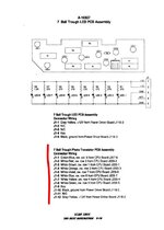
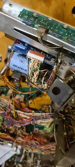
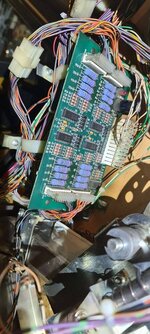
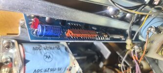
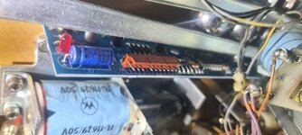
My issue is that during a little routine cleaning, I have noticed a "loose earth wire" coming off the 7 Ball trough PCB assembly A-16927 (yes I have been reading the manual). So I wondered where it belonged. It is not necessarily an earth wire either as it is coming out the back of the LED.
Does anyone know where this Earth Wire should route to?
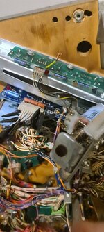
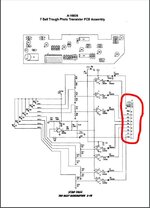
Then upon further inspection, I notice some poor joints. These are on the other very close circuit board A-16926 which is the "7 Ball Trough Photo Transistor Assy". This is shown on pages 63 and the wiring page 116 of the manual.
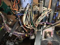
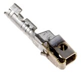
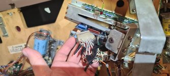
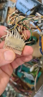
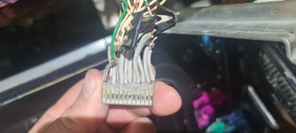
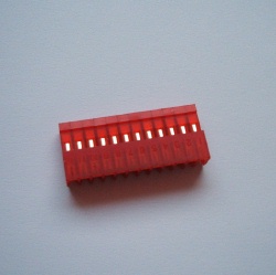
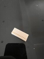
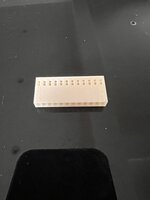
These dodgy wiring joints are insulated only by a single folded piece of electrical tape which after many years, glue has softened and it is falling off so now no protection. And so, I was thinking this looks an easy fix to make things right by buying a new 12 point connector socket and punching the original loom into it.
(Note, it is hard for me to be certain I would be punching the wires into this new socket as the original is obscured by some jelly type materail used in the suspect repair. I am sure this worked well, it still looks good condition).
I am now wondering if this is indeed a sub-par repair, or is it beefed up wiring to strengthen the original as it was demanding on the original parts?
All I needed to do was to take careful note of the wires coming out of the jelly joint and their relation to ports 1-12 on the connector block. This is where it got interesting (and note I am a total newbie at electronics). And so I though I better also confirm with the manual.
What I noticed is that J1-9 on the connector block says "Key" and J1-11 says "N/C"
Both ports are empty, and so N/C = no connection right?
But what is Key? Should that be empty?
All other wired ports seem to be correct, they all have 2 of the correct coloured wires attached with the exception of "J1-1", this has just one of the correct colour wire.
Also, is it correct to have just 1x Solid Green wire going to J1-1?
Thanks in advance if anyone knows the answers.
I think I need to start a new thread for this issue, originally I had posted it on my speaker wire issue, but this seems like a potential banana skin of an issue. In fact I am hesitant to ask as I could just repair like for like and everything would work just as it is, which to my knowledge is everything works.
My issue is that during a little routine cleaning, I have noticed a "loose earth wire" coming off the 7 Ball trough PCB assembly A-16927 (yes I have been reading the manual). So I wondered where it belonged. It is not necessarily an earth wire either as it is coming out the back of the LED.
Does anyone know where this Earth Wire should route to?

Then upon further inspection, I notice some poor joints. These are on the other very close circuit board A-16926 which is the "7 Ball Trough Photo Transistor Assy". This is shown on pages 63 and the wiring page 116 of the manual.
These dodgy wiring joints are insulated only by a single folded piece of electrical tape which after many years, glue has softened and it is falling off so now no protection. And so, I was thinking this looks an easy fix to make things right by buying a new 12 point connector socket and punching the original loom into it.
(Note, it is hard for me to be certain I would be punching the wires into this new socket as the original is obscured by some jelly type materail used in the suspect repair. I am sure this worked well, it still looks good condition).
I am now wondering if this is indeed a sub-par repair, or is it beefed up wiring to strengthen the original as it was demanding on the original parts?
All I needed to do was to take careful note of the wires coming out of the jelly joint and their relation to ports 1-12 on the connector block. This is where it got interesting (and note I am a total newbie at electronics). And so I though I better also confirm with the manual.
What I noticed is that J1-9 on the connector block says "Key" and J1-11 says "N/C"
Both ports are empty, and so N/C = no connection right?
But what is Key? Should that be empty?
All other wired ports seem to be correct, they all have 2 of the correct coloured wires attached with the exception of "J1-1", this has just one of the correct colour wire.
Also, is it correct to have just 1x Solid Green wire going to J1-1?
Thanks in advance if anyone knows the answers.


 I don't have that trough style in any of my current games so can't check mine.