What's new
Pinball info

Register a free account today to become a member! Once signed in, you'll be able to participate on this site by adding your own topics and posts, as well as connect with other members through your own private inbox!

STTNG Help Required

Marcel

Site Supporter
Joined
Feb 26, 2017
Messages
612
Location
Huddersfield
Hi Guys,

I think I need to start a new thread for this issue, originally I had posted it on my speaker wire issue, but this seems like a potential banana skin of an issue. In fact I am hesitant to ask as I could just repair like for like and everything would work just as it is, which to my knowledge is everything works.

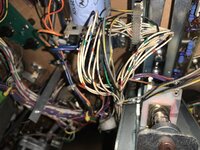
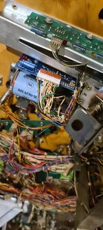
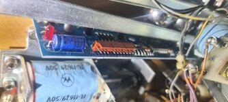
My issue is that during a little routine cleaning, I have noticed a "loose earth wire" coming off the 7 Ball trough PCB assembly A-16927 (yes I have been reading the manual). So I wondered where it belonged. It is not necessarily an earth wire either as it is coming out the back of the LED.
Does anyone know where this Earth Wire should route to?

Loose Earth.jpg

Then upon further inspection, I notice some poor joints. These are on the other very close circuit board A-16926 which is the "7 Ball Trough Photo Transistor Assy". This is shown on pages 63 and the wiring page 116 of the manual.

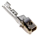
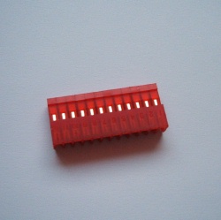
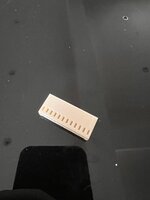
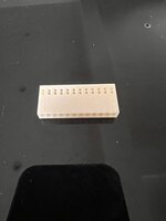
These dodgy wiring joints are insulated only by a single folded piece of electrical tape which after many years, glue has softened and it is falling off so now no protection. And so, I was thinking this looks an easy fix to make things right by buying a new 12 point connector socket and punching the original loom into it.
(Note, it is hard for me to be certain I would be punching the wires into this new socket as the original is obscured by some jelly type materail used in the suspect repair. I am sure this worked well, it still looks good condition).

I am now wondering if this is indeed a sub-par repair, or is it beefed up wiring to strengthen the original as it was demanding on the original parts?

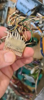
All I needed to do was to take careful note of the wires coming out of the jelly joint and their relation to ports 1-12 on the connector block. This is where it got interesting (and note I am a total newbie at electronics). And so I though I better also confirm with the manual.

What I noticed is that J1-9 on the connector block says "Key" and J1-11 says "N/C"

Both ports are empty, and so N/C = no connection right?
But what is Key? Should that be empty?

All other wired ports seem to be correct, they all have 2 of the correct coloured wires attached with the exception of "J1-1", this has just one of the correct colour wire.
Also, is it correct to have just 1x Solid Green wire going to J1-1?

Thanks in advance if anyone knows the answers.

Empty  J1-9 (Key).jpg
 
Not sure what’s been going on but that Earth wire is a bodge and has been added .

Key - Connectors are often keyed to prevent you putting them in wrong place or incorrectly . The header on the board will have a pin missing and the female connector will have a small plastic blanking pin in corresponding position .

N/C - yup not connected
 
Thanks Grizz,

That makes sense. I just been looking at other LED's on other boards, none have wires coming out back. So I feel it could be removed.
Although I'm scared to heat a circuit board.

As for the jelly plug, it's not such great condition. Defo need to replace it, I'll dismantle after the dogs walk and see what part is buried within the jelly to get it ordered.
 

Attachments

  • 16514881561754546237513743397620.jpg
    16514881561754546237513743397620.jpg
    54.2 KB · Views: 7
Looks like you have wires soldered to that other connector also , and the board def been hacked about .

Those trough boards often had issues over time - cracked joints, components failing , so not unusual tbh - though that’s some shonky handiwork there. That jellyfish horror show really is something 😮

I would be very tempted to install new connectors and get new boards from Pinball Heaven (or wherever has them) - they aren’t too expensive and I believe are an improved more reliable design also.
 
Looks like you have wires soldered to that other connector also , and the board def been hacked about .
Yes, atm, it looks to me like some repairer has brought along a 12 pin connector with 12 pre-soldered wires on it in order to make an on-site repair go quicker and easier as instead of needing to re-solder 12 (actually 10) wires to a new connector which would be detailed intricate work, they have the easier to manage 12 tails ready to solder to the loom.

Lazy workmanship I guess. And that is "if" it should be a soldered connector.

The wires are not soldered - the originals are IDC .... the wire pushed into place with a tool (or at a push a flat blade driver)

Like these ...


If you search on here or generally you'll see loads of info on connectors ....it's a much discussed topic in pinball :D
 
These are the replacement trough optos I installed. Good quality and worked a treat.
 
The wires are not soldered - the originals are IDC .... the wire pushed into place with a tool (or at a push a flat blade

Thanks all,

So I decided to remove the rogue earth wire from the first PCB (the green PCB), went well and machine still works perfectly. My thoughts on buying a replacement is that I might as well spend the money when it is broken.

Just for my interest I cut back some jelly off that other PCB connector block.
Not sure why this PCB is blue, but presumably it's already an upgrade/replacement of the original.

Blue PCB Board.jpg

Will an IDC connector still fit this board?
(It is still 0.1" pitch x 12 way)

Seems they've used a soldered block just because it fits and they had one spare, unless they have just soldered a push fit, I am not familiar enough with the blocks to know. Here is an image of the cut back bodge.

Soldered Jelly Connector.jpg
 

Attachments

  • 20220502_154446.jpg
    20220502_154446.jpg
    85.7 KB · Views: 5
Pinball mania is out of stock on 12 way x 0.1", has anyone any other suggestions please? Seems shipping could cost several times the item cost.

Pinball Heaven has this one, image has 12 way pictured, but is this the push in wire connection type and will it be 12-way on arrival?
 
Last edited:
Pinball mania is out of stock on 12 way x 0.1", has anyone any other suggestions please? Seems shipping could cost several times the item cost.

Pinball Heaven has this one, image has 12 way pictured, but is it this the push in type and will it be 12-way on arrival?
It looks like it is , and is 12 way. Just check with PH tomorrow.

Checked my spares - unfortunately no IDC ones, only have the 12 way 0.1” that uses crimps .

https://www.pinballshop.nl have stock …. I ordered small part from NL recently and it was cheap shipping and here in 3 days.
 
Checked my spares - unfortunately no IDC ones, only have the 12 way 0.1” that uses crimps .
Very nice of you to check thanks Grizz. No worries, I'll call PH tomorrow.

On the topic of crimped v push in, what is your stance?
Just general interest here after seeing a discussion on it elsewhere.
 
Very nice of you to check thanks Grizz. No worries, I'll call PH tomorrow.

On the topic of crimped v push in, what is your stance?
Just general interest here after seeing a discussion on it elsewhere.
IDC are fine if done correctly and def less of a faff. I have done plenty never had issues. Some folk prefer to crimp everything and believe IDC the devils work though 😁

Crimps are generally considered a better connection - as long as done properly, you need the right tool. And considered better for connectors where current draw might lead to heat build up …. the classic example being the general illumination connectors .
 
You know when you wish you hadn't started a job. Well I collected my 12 way 0.1" IDC connector from my local store today but the easy job became a pain in the butt. My connector only has enough depth for one wire to press in.
My loom has 2 wires that need to be inserted into each port and so I have a problem.

Admittedly my IDC connector didn't come from a pinball dedicated shop, but I am guessing that even the pinball shops IDC connectors are just the same because my part is pretty similar to any images shown.

So, is there a workaround? I am not against the crimp version and that way, I could crimp 2 wires more easily into a socket at a guess. But I cannot find a 0.1" 12 way crimp version either.

Anyone have any bright ideas?
 
I have 12 way 0.1” crimp housings
 

Attachments

  • DFC00DC7-60D1-4995-A7D1-637420DF5B8E.jpeg
    DFC00DC7-60D1-4995-A7D1-637420DF5B8E.jpeg
    37.6 KB · Views: 4
  • 59C26891-64E9-49E1-8CBF-73D939D29A9A.jpeg
    59C26891-64E9-49E1-8CBF-73D939D29A9A.jpeg
    34 KB · Views: 3
You know when you wish you hadn't started a job. Well I collected my 12 way 0.1" IDC connector from my local store today but the easy job became a pain in the butt. My connector only has enough depth for one wire to press in.
My loom has 2 wires that need to be inserted into each port and so I have a problem.

Admittedly my IDC connector didn't come from a pinball dedicated shop, but I am guessing that even the pinball shops IDC connectors are just the same because my part is pretty similar to any images shown.

So, is there a workaround? I am not against the crimp version and that way, I could crimp 2 wires more easily into a socket at a guess. But I cannot find a 0.1" 12 way crimp version either.

Anyone have any bright ideas?

Should there be wires doubled up there ?:hmm: I don't have that trough style in any of my current games so can't check mine.

You have the manual right ?

Capture1.JPG

Capture.JPG
 
This may help, will be fiddly at 0.1"

Thanks astyy, very helpful thanks.

Should there be wires doubled up there ?:hmm: I don't have that trough style in any of my current games so can't check mine.

You have the manual right ?

Hi again Grizz, yes I have the manual ta, all wire colour coding is correct in my machine also.

Perhaps before the bodge was done, it was looped? As this is the end of the wiring loom. And so one loop became two ends?

I am a little confused as to the crimp wire housings. Do I specifically need Molex?

I found these at my local, I am thinking I may as well get the crimps and go that way so I can eventually replace them all.
 
That J1 contains several switch matrix column and row wires which commonly daisy chain, so two wires of same colour at the terminal.

Pinball mania has the connector etc.
Connector housing 0.1", add keying plug - https://pinparts.co.uk/products/crimp-housing-0-dot-156-pitch-choose-size
Crimps for 0.1" housing , get some spares to practice - https://pinparts.co.uk/products/crimp-terminal-0-dot-156-pitch-choose-type
Crimp tool - https://pinparts.co.uk/products/ht-225d-crimp-tool-for-molex-crimp-pins-awg-18-22-24-30
 
Thank you everyone, looks like you guys have helped me out, mucho grassyass.

That J1 contains several switch matrix column and row wires which commonly daisy chain, so two wires of same colour at the terminal.

Pinball mania has the connector etc.
Connector housing 0.1", add keying plug - https://pinparts.co.uk/products/crimp-housing-0-dot-156-pitch-choose-size
Crimps for 0.1" housing , get some spares to practice - https://pinparts.co.uk/products/crimp-terminal-0-dot-156-pitch-choose-type
Crimp tool - https://pinparts.co.uk/products/ht-225d-crimp-tool-for-molex-crimp-pins-awg-18-22-24-30

Brilliant, I'll be placing the order of all that lot soon.
Does anyone know, is there a list of all plugs and sizes available anywhere or kits available per game as I'm thinking I may do the lot to keep game fresh. Or is that daft?
 
Only recrimp if you have to - if it aint broke.............

Cheap crimps are like 1p each or less.

Decent crimps are 10-50p+ each, Ive started using these molex high pressure crimps as they make a really good connection with the pin. They are fully enclosed end so the pin makes contact on both sides.
 

Attachments

  • 6f555a5ce8694186b749bd101ac4d85d257b0b61.jpg
    6f555a5ce8694186b749bd101ac4d85d257b0b61.jpg
    51.8 KB · Views: 6
💥 💥 Job Done 💥 💥

Thank you everyone for your guidance, I couldn't have completed it without your guidance.

Blooming heck getting 2 x 22AWG wires into the 0.1" molex was difficult but eventually I found a working system.
 

Attachments

  • 20220509_210536.jpg
    20220509_210536.jpg
    83.6 KB · Views: 14
I know someone said if it ain't broke don't fix it, but this pcb, although working, looks like it has been rescued from a swamp.

There are x4 10 pin IDC connectors attached and they have sligh browning as if about to (or have previously) melt.

Thing is, if I can connect x2 wires to a single Molex, I should be easily capable of attaching x1 cable and upgrading/renewing to molex (if indeed it is upgrading), just in case something is starting to burn up.

BUT, this is where it gets stupid, is there a way to clean my pcb?
Looking in the Red LED area and next to it, that Black capacitor/resistor, they look so dirty, I could imagine they were once upon a time sat in a mud bath.

Has anyone seen this level of dirt/dust before, its odd as the playfield is original and is also fantastic condition.

20220509_210707.jpg
 
Dust and dirt won’t hurt that board, trying to clean it could.

it not broken like you said 🤪
 
Back
Top Bottom