What's new
Pinball info

Register a free account today to become a member! Once signed in, you'll be able to participate on this site by adding your own topics and posts, as well as connect with other members through your own private inbox!

SOLVED: Various coils not showing in test menu for BoP after major blowout!

Andy B

Site Supporter
1 10 Years
Joined
Oct 6, 2014
Messages
1,424
Location
Hull. England.
Working on a BoP.

Guy that has asked me to look at it for him said ball was not shot out by under playfield kicker (Solenoid 3) and fuse F104 had blown on the PPB board so, not knowing what he was doing, he replaced it with a standard 13 amp household fuse!

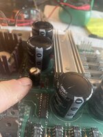
When he switched the game back on again he noticed smoke coming out of the back and a "big black thing" in the back glowing red hot (capacitor C11).

I had PPB out and tested all transistors. All tested good barring Tip 36c and Tip 102 for ball eject (Solenoid 2) so replaced both and the diode and replaced F104.

Switched on. F104 blew immediately.

I am guessing that the fuse diagram in manual is incorrect as F104 is supposed to be for solenoids 9 to 16 BUT all solenoids 1 through 14 plus 27 are working HOWEVER, the following solenoids do not show up in the test menu:

8, 15 to 26 and 28.

I have never had anything like this before were solenoids are just not showing up in test menu so I am guessing it is one of the ICs that has gone?

Anyone had similar and can help please?

Thanks

Andy
 
I think he may have recalled incorrectly which capacitor was glowing and smoking 😊

This is C8.

Think I will replace C11 as well anyways since as that is bulging.

And both rectifiers.
 

Attachments

  • 286E11CB-8661-4142-8E49-AD306C948EB1.jpeg
    286E11CB-8661-4142-8E49-AD306C948EB1.jpeg
    89.5 KB · Views: 25
Last edited:
OK. Replaced the capacitors, rectifiers, diodes, transistors on PPB board. Locking on coils sorted.

Game was not registering ball drain - diagnosed that whole row of switches out. Moved switch connector from J208 to J209. That sorted that.

Replaced F104. Switched on. F104 blows again!

Tested coils. All working fine except 8, with 15 to 26 not showing up in coil test as before. After much head-scratching, worked out that coils 8, 15 and 16 are in the head and you test those via specific head test menu. 17 to 24 are flashers - tested through the flasher tests - doh!. 25 and 26 are data ports.

So that only left coil 27. Coil 27 is the face relay but that is not working, Also in head test mode, face will not rotate anti-clockwise. Playing a game, it gets mixed up with which face was showing - not that I've ever played the game before but it was coming up with messages that didn't fit the face that was showing :-). So I figure F104 must be dedicated fuse for head relay. Lot of Youtube vids suggest reflowing pins on relay board. Did that. Tested relay using external 12V power supply. Works fine. Replaced diode on relay board. Replaced F104. Blows again!

So I just need to confirm F104 is fuse for head relay and only thing left to do then is replace relay - though, like I say it works fine with external 12v supply.
 
  • Like
Reactions: JT.
If the relay works fine with an external supply then it's unlikely to be the culprit.

It might be worth checking Q20 (head motor) and Q22 (motor relay) again in case they've blown with the fuse.

I'd find the motor regulator board (A-13892-2) and check the voltages. I'd leave J2 disconnected, check you have 20v on pin 1 of J1 and 12v on pin 1 of J2.

Also check the outputs of J107 pin 2 and J122 pins 4 and 5 (motor relay (sol 27) and head relay (sol 28)).
 
Thanks. The Head Motor Relay is working now so clearly that's not F104.

Coils 9 to 16 are working fine also.

I now have a problem with coils 1 to 4 which are only working intermittently (with no fuses blown). There is no wire to J107 pin 2.

Confused...
 
And now it's 1 to 8 not working. In diagnostics or gameplay. All fuses fine (barring F104).

Time for bed me thinks...
 
Just curious as it is so so easy to be done ,the ribbon cables connected correctly ?
Thanks. I reseated the cable and now everything is working fine (with F104 blown) except when I play a game with glass off, rolling the ball up the ramp to the face:

Ball lands in mouth “I can speak” - ball is kicked out, held briefly in ball lock gate then released to left flipper. Face rotates to “eyes” face.

Ball lands in left eye “Partial Optical Link”. Ball held in eye socket.

Ball lands in right eye “I can see”. Both balls released from eyes and roll in to ball lock gate.

Stand around, twiddle my thumbs, wait for balls to roll out of ball lock gate or more likely 3rd ball to be kicked out from trough ready to be played (I’ve never played this game before so don’t know what’s supposed to happen at this point but clearly something is not!) but nothing happens. Solenoids fire after a while like it’s looking for a lost ball.
It’s only a two ball multiball mate so make sure there aren’t too many balls in the game
 
It’s only a two ball multiball mate so make sure there aren’t too many balls in the game
Thanks.

I diagnosed the failure to start multiball as a dodgy ball lock switch. Was not registering the second ball entering lock.

Played a few games with glass off. Got two ball multiball.

Now it's blowing F105!!!
 
As you don’t know the history of this machine double check all connectors are going to the correct spot , then try what @Moonraker said !!
Thanks. I figured it wasn't a motor drive board issue as the head motor and relay were working fine. It was like it wasn't recognizing that the 2nd ball was locked and sure enough it was the second ball switch which was not working so I swapped that out. Played a few games with glass off. Got 2 ball multiball no problems.

Switched it off and then back again after a wait. Now it's blowing F105 all the f@;~ing time!!
 
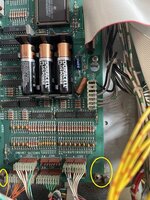
Could be that you're missing (or need) the surge protector for motors which is a standard fit for a Stern. And/Or you have battery corrosion issues... post a picture of the board area around where the battery goes on the mpu to help rule that out.
 
Could be that you're missing (or need) the surge protector for motors which is a standard fit for a Stern. And/Or you have battery corrosion issues... post a picture of the board area around where the battery goes on the mpu to help rule that out.
Thanks for sticking with me in this. Appreciate it!

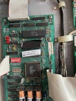
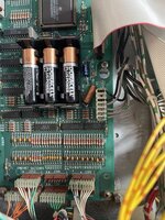
Photo uploaded. All looks good and the guy said he knew he needed to change batteries regularly which he had been doing.
 
Photos of mpu
 

Attachments

  • 5007FCD6-D6BB-4E48-997C-27D1A3D8265D.jpeg
    5007FCD6-D6BB-4E48-997C-27D1A3D8265D.jpeg
    151 KB · Views: 23
  • DCBCB946-98A7-4C88-B2C1-8F754FA941C0.jpeg
    DCBCB946-98A7-4C88-B2C1-8F754FA941C0.jpeg
    162.6 KB · Views: 23
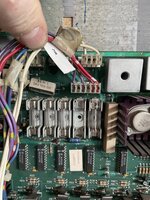
And a photo of the infamous J107 which has nothing at pin 2. Violet/yellow wire goes to pin 3 on this machine.
 

Attachments

  • 77C4802A-4356-4AD9-BE2A-60F75FC0704F.jpeg
    77C4802A-4356-4AD9-BE2A-60F75FC0704F.jpeg
    139.2 KB · Views: 29
That's a replacement board. You can see the battery corrosion around the lower mounting screws and on the screws themselves. That will be stopping a good earth and needs cleaning / replacing. This means that the connectors may well be corroded, causing the issues you're experiencing...

Check out the female connectors here and see if yours look similar:
 
And a photo of the infamous J107 which has nothing at pin 2. Violet/yellow wire goes to pin 3 on this machine.
You're right, page 3-5 (119/121 of pdf) is wrongly showing violet/orange wire to pin 2.

Page 3-16-c shows no connection for the violet/orange to J107, so they changed it at a later date.
 
Corrosion evidence circled and ought to be cleaned up / screws replaced. Remember to check all those female connectors whilst you're there, just one green or mushy coloured pin could be the cause.

Bride MPU.jpeg
 
You're right, page 3-5 (119/121 of pdf) is wrongly showing violet/orange wire to pin 2.

Page 3-16-c shows no connection for the violet/orange to J107, so they changed it at a later date.

I wonder what the issue is with F104 then. Manual says solenoids 9 - 16. You say solenoids 9 - 16. Every post that comes up on Google says solenoids 9 - 16 but 9 - 16 work without F104 in this machine!
 
That's because there's a secondary feed that's by passing F104, without looking at a circuit diagram it's hard to say but I think it might be something like the solenoid secondary (F112).

F104 works both ways and it's probably being blown by which ever BR and/or capacitor that it's connected to. It's normally quite easy to follow the tracks to see which Cap and BR (and/or use a meter for continuity testing to confirm if in doubt).

Try reading this and read down to the end of the Failed Bridge Rectifier piece:
 
That's a replacement board. You can see the battery corrosion around the lower mounting screws and on the screws themselves. That will be stopping a good earth and needs cleaning / replacing. This means that the connectors may well be corroded, causing the issues you're experiencing...

Check out the female connectors here and see if yours look similar:
Thanks.

I cleaned up the rust and put new screws in. few pins on J208 connector have a green tinge to them but nothing too bad. Whilst testing the coils again, noticed the wires from the test enter button where touching each other so I moved those apart. I have no issues with the switches now (for the time-being!)
 
That's because there's a secondary feed that's by passing F104, without looking at a circuit diagram it's hard to say but I think it might be something like the solenoid secondary (F112).

F104 works both ways and it's probably being blown by which ever BR and/or capacitor that it's connected to. It's normally quite easy to follow the tracks to see which Cap and BR (and/or use a meter for continuity testing to confirm if in doubt).

Try reading this and read down to the end of the Failed Bridge Rectifier piece:
Thanks.

The bridge rectifier that feeds F104 was one of the 2 I replaced. It is testing good.

Capacitor feeding F104 is C8 which was the exploded one I replaced.

Went back to the beginning: Removed J127. Fuse blowing. Removed J127 and J107. Fuse blowing. So clearly a board fault.
 
Last edited:
Back
Top Bottom