On my new Hook project my first major problem was the flipper/coil fuse continually blowing on power up, I noticed that the kicker coil fired/stuck on power up seemingly caused by a shorted driving transistor. With this coil disconnected (leave the two HOT wires typically two connected) it didn't fuse and everything else worked. The transistor tested bad, the coil good so I replaced the former but then was back to square 1 - coil stuck, fuse blowing, transistor toasting etc. I finally found out (on moonrakers tip) that the coil was actually bad when under use. This was a real head scratchier at the time and took ages to sort - something testing good is bad. You could have a similar problem with something on J8.One thing that might help is page 88 of the manual which has the list of coils that are attached to J8. Some of these can be disconnected to isolate which area might be broken.
Pinball info
You are using an out of date browser. It may not display this or other websites correctly.
You should upgrade or use an alternative browser.
You should upgrade or use an alternative browser.
In Progress Sega Star Wars Trilogy Shop Log - Beginner level
- Thread starter jww
- Start date
Hiya Astyy and thanks for your advice, that has definitely given me something to think about. I have added to my list of things to learn about and get/make is some out of circuit testing thing as well as to look at the transistors.
I'll post an update next in a separate post to keep things separate, as I've been investigating slowly.
Cheers,
Johnny
I'll post an update next in a separate post to keep things separate, as I've been investigating slowly.
Cheers,
Johnny
Hello all,
Ok, I've been thinking, looking and planning where to go from here with my current skills.
So, we know so far that with J8 connected to the motherboard in the top box, that fuse f21 blows, for 50v DC coils.
I've made a spreadsheet for all 7 coils, listing info about them from the manual, and my observations, notes, test results. I may have some unnecessary fields, or missed others, but it's a start.
First coil I decided to pick was the Auto Launch named coil, as it was easy to access and looked quite sooty.
Here's a pic of it, top right of the picture:

Putting my multi-meter on it, with the meter on the ohms setting 200, I ready 3.9 from the coil no matter what way around I connect the meter's probes. This is above the 3ohm number I've read that is a rough minimum for a working coil, so this one /appears/ to be ok.
I note that this is a lower ohm value than any of the other coils on this J8 connector that i tested. Once i figure out a way to paste/import my spreadsheet into this post, i'll do that at a later time so you can see my progress/results.
This Auto Launch coil only has 2 wires in total connected to it.
QUESTION1: Since this coil only has 2 wires total, if i I want to remove the coil to test out of circuit, do I just desolder the 2 wires from the coil and separately tape them up so they can't short together/against anything else? If I'm understanding correctly, I should only keep 2x hot wires soldered together when removing a coil if I have them (I think this would be a 3 wire coil, not a 2 wire like this one). I hope that's correct, if not please let me know.
Next I figured I could do some things safely without powering on the machine. From reading, I should really test the diodes, and that they can only be tested out of circuit. With that in mind I decided that I will replace all coils+diodes in the machine, but first will try to find the troublesome things as a learning process, while being as safe as possible.
I've desoldered the 2 wires from coil:2, and cut out the diode, taped the wires up separately and will wait for answers to my question above before considering turning on the machine. I've tested that coils resistance again with my meter and it's a little lower but still above 3.
I've read about a bit about testing diodes and on the diode setting on my meter, I get a reading one way, not the other as well as no continuity beep, so I think that diode was possibly fine. No matter, I have learnt a lot just by getting to this stage, and diodes are cheap so will get some ordered (QUESTION2: Or do new coils come with diodes already fitted?)
I thought I could paste from my spreadsheet into this post, but it's not previewing, so forgive the **** formatting, have just typed them in instead:
Coil: 2
(INFO BELOW = FROM MANUAL)
Description: Auto Launch
Drive Transistor (D.T): Q2
D.T Control line colour: BRN-RED
D.T Contol Line Connect: J8-P3
Power Line Colour: YEL-VIO
Power Line Connection: J10-P4/5
Voltage: 50v
Coil GA/Turn or Bulb Type: 23-700 // 090-5022-00T
Location: Above playfield
(INFO BELOW = JOHNNY'S RESULTS/OBSERVATIONS (THEREFORE PROLLY WRONG/STUPID)
Coil In Machine Details: BLACK BEAST 23-700. 090-5022-0T OR -01, messy label writing
Ohm Measurement : 3.9ohms (tested while coil in machine untouched by me)
Diode?: Yes - markings: in4004,g1636m i think, fecking small writing
test diode: yes with multimeter on diode+continuity setting. one way round it gives '569', other way around '1' and does not make the continuity beep sound
test of coil without diode attached or in machine: 3.6ohms
Conclusion thoughts about coil:2 so far:
* Next need to build/buy an adjustable psu thingy so i can test coils firing out of machine (just thoughts atm)
* buy new diode and replace one I cut off
* clean up, but do not lube anything and check plastic shaft if needs replacing
Here's a picture of that unit removed from the machine:

Doesn't sound that much progress now I've written that up, but I've have spent some enjoyable time reading up about diodes/coils and watching testing videos on youtube to learn and making the spreadsheet which I can't work out how to paste in just yet, has been fun an interesting, as well as time consuming.
I did find that the x-wing launcher coil did not have a diode on it, unlike every other coil on this J8 connector, that stood out on my spreadsheet so before bed tonight I'm going to read the manual and see what it says about that x-wing coil.
Have a great night everyone, seeya soon")
Cheers,
Johnny
Ok, I've been thinking, looking and planning where to go from here with my current skills.
So, we know so far that with J8 connected to the motherboard in the top box, that fuse f21 blows, for 50v DC coils.
I've made a spreadsheet for all 7 coils, listing info about them from the manual, and my observations, notes, test results. I may have some unnecessary fields, or missed others, but it's a start.
First coil I decided to pick was the Auto Launch named coil, as it was easy to access and looked quite sooty.
Here's a pic of it, top right of the picture:
Putting my multi-meter on it, with the meter on the ohms setting 200, I ready 3.9 from the coil no matter what way around I connect the meter's probes. This is above the 3ohm number I've read that is a rough minimum for a working coil, so this one /appears/ to be ok.
I note that this is a lower ohm value than any of the other coils on this J8 connector that i tested. Once i figure out a way to paste/import my spreadsheet into this post, i'll do that at a later time so you can see my progress/results.
This Auto Launch coil only has 2 wires in total connected to it.
QUESTION1: Since this coil only has 2 wires total, if i I want to remove the coil to test out of circuit, do I just desolder the 2 wires from the coil and separately tape them up so they can't short together/against anything else? If I'm understanding correctly, I should only keep 2x hot wires soldered together when removing a coil if I have them (I think this would be a 3 wire coil, not a 2 wire like this one). I hope that's correct, if not please let me know.
Next I figured I could do some things safely without powering on the machine. From reading, I should really test the diodes, and that they can only be tested out of circuit. With that in mind I decided that I will replace all coils+diodes in the machine, but first will try to find the troublesome things as a learning process, while being as safe as possible.
I've desoldered the 2 wires from coil:2, and cut out the diode, taped the wires up separately and will wait for answers to my question above before considering turning on the machine. I've tested that coils resistance again with my meter and it's a little lower but still above 3.
I've read about a bit about testing diodes and on the diode setting on my meter, I get a reading one way, not the other as well as no continuity beep, so I think that diode was possibly fine. No matter, I have learnt a lot just by getting to this stage, and diodes are cheap so will get some ordered (QUESTION2: Or do new coils come with diodes already fitted?)
I thought I could paste from my spreadsheet into this post, but it's not previewing, so forgive the **** formatting, have just typed them in instead:
Coil: 2
(INFO BELOW = FROM MANUAL)
Description: Auto Launch
Drive Transistor (D.T): Q2
D.T Control line colour: BRN-RED
D.T Contol Line Connect: J8-P3
Power Line Colour: YEL-VIO
Power Line Connection: J10-P4/5
Voltage: 50v
Coil GA/Turn or Bulb Type: 23-700 // 090-5022-00T
Location: Above playfield
(INFO BELOW = JOHNNY'S RESULTS/OBSERVATIONS (THEREFORE PROLLY WRONG/STUPID)
Coil In Machine Details: BLACK BEAST 23-700. 090-5022-0T OR -01, messy label writing
Ohm Measurement : 3.9ohms (tested while coil in machine untouched by me)
Diode?: Yes - markings: in4004,g1636m i think, fecking small writing
test diode: yes with multimeter on diode+continuity setting. one way round it gives '569', other way around '1' and does not make the continuity beep sound
test of coil without diode attached or in machine: 3.6ohms
Conclusion thoughts about coil:2 so far:
* Next need to build/buy an adjustable psu thingy so i can test coils firing out of machine (just thoughts atm)
* buy new diode and replace one I cut off
* clean up, but do not lube anything and check plastic shaft if needs replacing
Here's a picture of that unit removed from the machine:
Doesn't sound that much progress now I've written that up, but I've have spent some enjoyable time reading up about diodes/coils and watching testing videos on youtube to learn and making the spreadsheet which I can't work out how to paste in just yet, has been fun an interesting, as well as time consuming.
I did find that the x-wing launcher coil did not have a diode on it, unlike every other coil on this J8 connector, that stood out on my spreadsheet so before bed tonight I'm going to read the manual and see what it says about that x-wing coil.
Have a great night everyone, seeya soon
Cheers,
Johnny
This just sounds toooo much like the fusing problem on my Hook even at the same Kicker location. Yes this one has only two wires as its the end of the chain (being furthest from the backbox), the live/hot wire is daisy chained between the coils in front of this one, so if you remove one of those you must keep the same colour wire joined. The coils are activated by the other wire being switched to ground.QUESTION1: Since this coil only has 2 wires total, if i I want to remove the coil to test out of circuit, do I just desolder the 2 wires from the coil and separately tape them up so they can't short together/against anything else? If I'm understanding correctly, I should only keep 2x hot wires soldered together when removing a coil if I have them (I think this would be a 3 wire coil, not a 2 wire like this one). I hope that's correct, if not please let me know.
On mine the Black Beast ones you have do, but I bought different ones from pinball mania that don't so don't rely on it. As you point out they are super cheap and used all over - so buy a stock of 1N4004. The important thing with diodes is that they must be fitted the right way round.QUESTION2: Or do new coils come with diodes already fitted?)
The driving transistor is likely damaged too - these normally test bad if so and are easily tested with your DMM - with machine OFF - the procedure is documented here;
http://techniek.flipperwinkel.nl/desega/index2.htm
The good thing is as you have lots of the same component in banks you get the feel of what they should read by testing the ones around it.
Finally that coil is probably a 23-800 and if so the resistance should read 4.5 Ohms, yours sounds low and also sooty not good.
What is the machine doing now you've removed the coil?
Dean, have a good study of page 29 in the manual - isn't this the coil you've removed?

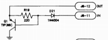
Then its the TIP36C - Q1 on the PPB board that you want to be testing, This is the section of the PPB PCB on page 65. There is a pre-driver Q23 on the CPU but concentrate on the PPB first.

and on same page it shows you where these components are physically on the board just below J8

I'm not super knowledgeable on this stuff but I've been down a similar path on a very similar DE machine.
You will get there and its worth it - this is STAR WARS after all!!!
Then its the TIP36C - Q1 on the PPB board that you want to be testing, This is the section of the PPB PCB on page 65. There is a pre-driver Q23 on the CPU but concentrate on the PPB first.
and on same page it shows you where these components are physically on the board just below J8
I'm not super knowledgeable on this stuff but I've been down a similar path on a very similar DE machine.
You will get there and its worth it - this is STAR WARS after all!!!
Attachments
Hello astyy, all,
Thanks for the answers to my questions previously, I appreciate that.
I managed to pickup two diodes from Maplins and will get more once they have more in stock. Also picked up some heat-shrink tubing and a fibre glass pen:

I had not turned on the machine after removing the auto-launch coil, but once I got the answers confirming that it was safe, I did so, and F21 blew again. Ok, so I've ruled that coil out now, 6 to go. Progress!
Thank you for the schematics pictures and advise. I got very confused at first as I couldn't match your page numbers with my real manual, but have since looked at the pdf version onilne here and those page numbers seem to match up. I must admit the schematic stuff is a little beyond me atm, but the more I look and learn, the more of them I can understand slowly. I can recognise some components now in diagrams, so pleased with that!
I've copied pictures below from the bits I think are relevant. I just looked for anything that said J8 and went from there.
This shows everything connected to the J8 connector:

This is the schematic from the io board:

another ioboard j8 schematic:

Some info about testing:

So, I've read that over a few times and am a little confused.
I'm not sure if it's meaning I can test the MOSFET with the J8 Connector connected or not. Also if the machine needs power or not when doing that test. Sorry, I'm being stupid - am having to learn as I go and am content with being patient and safe with my investigation.
While looking over all the photos that I took, I saw in this thread in July that previously I had taken a photo of a slightly brown area, around the connector, but not thought too much of it. So, went for a closer look and it appears rather obvious now that a problem has happened:


Observations show a burnt up resister? (yellow bead thing) next to Q5, so I'm currently thinking that Q5 coil was to blame at present. Interestingly Q5 is the X-Wing canon, which is on J8 and I had noticed previously that this coil does not have a diode on it. One of the reasons I created this shop log to begin with was because the canon wasn't working properly, so this is starting to make sense, I think. From reading the advice given in this thread and the supplied link re: sega hardware investigation, I think everyone is saying if a diode breaks, or is missing, then it can break a transistor.
So that's where I'm at currently. I won't be turning the game on again soon as I don't like the burnt look on the io power driver board. I will be reading more about how to test those mosfet things, and if I need to have J8 connected to do so - as well as does it need to be powered up and a whole host of other questions swirling around my head. My un-educated hunch at present is that I need to test and possibly replace the mosfets in that area and some resisters too.
Despite finding damage, I am pleased as am continuing to learn and make progress. So there you go, that's the current status. I'm not sure I'm up for doing work on the ioboard myself, also not sure how to test despite reading, but will re-read that sega hardware testing page a good few more times before reporting back with some sort of suggested plan to see what people think.
Cheers,
Johnny
Thanks for the answers to my questions previously, I appreciate that.
I managed to pickup two diodes from Maplins and will get more once they have more in stock. Also picked up some heat-shrink tubing and a fibre glass pen:
I had not turned on the machine after removing the auto-launch coil, but once I got the answers confirming that it was safe, I did so, and F21 blew again. Ok, so I've ruled that coil out now, 6 to go. Progress!
Thank you for the schematics pictures and advise. I got very confused at first as I couldn't match your page numbers with my real manual, but have since looked at the pdf version onilne here and those page numbers seem to match up. I must admit the schematic stuff is a little beyond me atm, but the more I look and learn, the more of them I can understand slowly. I can recognise some components now in diagrams, so pleased with that!
I've copied pictures below from the bits I think are relevant. I just looked for anything that said J8 and went from there.
This shows everything connected to the J8 connector:
This is the schematic from the io board:
another ioboard j8 schematic:
Some info about testing:
So, I've read that over a few times and am a little confused.
I'm not sure if it's meaning I can test the MOSFET with the J8 Connector connected or not. Also if the machine needs power or not when doing that test. Sorry, I'm being stupid - am having to learn as I go and am content with being patient and safe with my investigation.
While looking over all the photos that I took, I saw in this thread in July that previously I had taken a photo of a slightly brown area, around the connector, but not thought too much of it. So, went for a closer look and it appears rather obvious now that a problem has happened:
Observations show a burnt up resister? (yellow bead thing) next to Q5, so I'm currently thinking that Q5 coil was to blame at present. Interestingly Q5 is the X-Wing canon, which is on J8 and I had noticed previously that this coil does not have a diode on it. One of the reasons I created this shop log to begin with was because the canon wasn't working properly, so this is starting to make sense, I think. From reading the advice given in this thread and the supplied link re: sega hardware investigation, I think everyone is saying if a diode breaks, or is missing, then it can break a transistor.
So that's where I'm at currently. I won't be turning the game on again soon as I don't like the burnt look on the io power driver board. I will be reading more about how to test those mosfet things, and if I need to have J8 connected to do so - as well as does it need to be powered up and a whole host of other questions swirling around my head. My un-educated hunch at present is that I need to test and possibly replace the mosfets in that area and some resisters too.
Despite finding damage, I am pleased as am continuing to learn and make progress. So there you go, that's the current status. I'm not sure I'm up for doing work on the ioboard myself, also not sure how to test despite reading, but will re-read that sega hardware testing page a good few more times before reporting back with some sort of suggested plan to see what people think.
Cheers,
Johnny
That's a capacitor and that area don't look pretty does it, that cap almost looks like it has blowout from elsewhere. I'll have a study of the manual and give you some more suggestions.Observations show a burnt up resister? (yellow bead thing) next to Q5
I'm also new to reading schematics and stuff so please those in the know correct me if i'm wrong, but there are two dead give aways that it's a cap that's blown and NOT a resistor:
1. Resistors always have a series of colour bands on them to denote their resistance. This site includes a nice little calculator you can use to work out the resistance based on the colour bands.
2. The notation on the circuit board itself confirms it's a capacitor. The part has a label to the left marked up C266 with the C standing for Capacitor.
3. And of course the schematic confirms it. If you look on the J8 schematic diagram you see the two symbols near to each other.
The resistors near the top look like this:
And capacitors like this:
Erm, obviously they can be rotated to be used in different orientations on the diagram but you get the idea.
Please keep posting though because it's only by reading stuff like this and watching Lukes (and others) videos that I learn and get the confidence to try more. I certainly would not have even contemplated stripping my Pin down to the extent I have if it were not for all the stuff i've learnt on here.
Question for those really in the know? Could it be a missing or failed diode on the coil has allowed voltage back up the line and fried the capacitor? I presume it's not gone all the way back to the U1 chip because if that had blown nothing that it drives would be working?
Last edited:
There's several issues with that board and I'd recommend sending it to someone who knows what to do.
Straight up I see C271 missing altogether, what looks like bad solder joints on Q8, Q1, Q5 and Q10.
Q5 may or may not be blown. C27 could have ended up like that from a previous Q5... Either way it probably should be replaced. R6 above it doesn't look to good.
Straight up I see C271 missing altogether, what looks like bad solder joints on Q8, Q1, Q5 and Q10.
Q5 may or may not be blown. C27 could have ended up like that from a previous Q5... Either way it probably should be replaced. R6 above it doesn't look to good.
Thanks astyy, Wiredworm and Moonraker for your advice.
In between real-life chaos I've been thinking about the best way forwards. Please forgive my numbered list, it's how I organise my thoughts.
1. Yes, I won't (and haven't) touched the ioboard (apart from replacing fuse f21) and would like to pay someone suitably skilled to repair it for me. While I can do basic soldering, this is too complex and too important a part for me to do repairs.
Does anyone have any advice on who I can ask re: repairs?
2. Is there any testing I can do without powering the board on in its current state? This whole process has introduced me to so many things I figured that I'd ask in case I can test the transistors or other stuff with it off and without any board soldering. Learning is always good.
3. That fuse blew for a reason and presumably was also why ioboard got damaged. What is worrying me is that I pay to get my board fixed, put it back in, only to have the same thing happen again.
is this thinking correct and that still outstanding is to find which coil caused it in the first place?
4. there are seven coils connected to j8, I think I've ruled out #2 auto launch by disconnecting it and fuse still blowing as described in an earlier post.
That leaves six to test.
I think I should not continue my plan with my ioboard in its current state. For ref, plan is disconnect a coil (keeping two hot/live wires together if found), put new fuse in and turn it on. If fuse blows, it's not the coil I just disconnected. If it doesn't, I've found the naughty one.
Am I correct in thinking I should not continue now I've found board damage?
Thanks in advance and sorry for all my questions. Sorry if I wind anyone up with my ignorance and incorrect terms for things. This machine is likely the best possession I will ever own. I just want to play on it and if I can do any of the fixing bits safely myself, as I'd like to learn.
Cheers,
Johnny
Sent from my iPhone using Tapatalk
Without doubt i'd be going to Luke Wells (@lukewells).Does anyone have any advice on who I can ask re: repairs?
Well worth watching his YouTube channel (ArcadeUK) too. Gives some insight into the work he does and it's a great way to learn new stuff.