What's new
Pinball info

Register a free account today to become a member! Once signed in, you'll be able to participate on this site by adding your own topics and posts, as well as connect with other members through your own private inbox!

In Progress Sega Star Wars Trilogy Shop Log - Beginner level

jww

Site Supporter
Joined
Aug 4, 2013
Messages
145
Location
Walmer
Hello,

Ok, I think I’m feeling more ready to start looking at my beautiful Sega Star Wars Trilogy pinball machine which is infused with the dark side and is being very rebellious.

Disclaimer: I really am a newbie. I’m a network engineer by trade and own a few arcade cabs and have done some /very/ /simple repairs and resto work. I also own a Bally Knockout and managed to solve one problem on it, but that was bloomin hard work, and it’s developed another problem since then and that depressed me so much I’ve left that alone now too. I am not a butcher or bodger, preferring instead to back away when I’m out of my depth, to do reading or ask questions, or simple multi meter reading to try to figure out what the smeg is going on. I’ve bought the manual for this machine and have been reading it but boy it is pretty hardcore. I think I understand 1% of it so far! I will get there, I’m just a bit slow and sometimes just need a gentle nudge in the right direction.

Apology 1: I talk a lot and regularly muddle my words so much that I convey the opposite thing to what I mean. Being misunderstood scares me to death, so please be patient with me and I’ll do my best.

NB: Pictures are at the bottom of this thread.

Problem 1

On the very first night of getting this game (ironically this was within a day of getting my Bally Knockout), during the first or second play on it, the display brought up an error saying x-wing cannon malfunction or similar, so I turned the machine off and ran away. This pinball is like having a real Ferrari to me, in that it’s so special to me, I don’t want to hurt it and do want to treat it with respect, only investigating and fixing things with great care. Hence turning it off and leaving it until I knew more.

NB: At this point I focused my attention on my Knockout table, as I wanted to learn more fixing skills on not-my-ferrari. If you can’t sleep, the thread about the Knockout is here http://www.pinballinfo.com/communit...azy-when-turned-on-doesnt-move-the-ball.7691/

Since then I’ve tried to read up about x-wing cannon problems but have not found much, except a single forum thread elsewhere out on the net saying that sometimes it just needs adjusting so that the microswitches are pressed in correctly. From my limited understanding they were saying the x-wing is on a post, with screws holding it in place. They seemed to be saying this could slip and cause it to rotate slightly, therefore not making contact with the micro switches properly when it rotates back to normal/home position.

This kinda makes sense as it was delivered vertical on a pallet from a lorry so I’m speculating it’s slipped a bit in transit possibly.

In the tech messages, section of the bios I can see it complaining about this unit


By gently touching the x-wing, pushing it back 2mm so it’s straight, facing the back head unit box thing, I can hear a microswitch under the play field ‘click’, which kinda suggests this has slip has happened - but I’m not sure. I forgot to video that tonight but will do so in the morning and post it up.

I can also see that underneath the x-wing there is what looks to be a twisted up paperclip holding a plastic bar in place. That can’t be right, surely.

I also noticed that the plastic bar is flimsy and wobbles up down and bends when very gently touched with my little finger. I’m wondering if this is the/an issue.

Problem 2

One of the next times when I turned it on briefly to go through the bios to try the diagnostic features to see if I could get any clues or more verbosity about the x-wing cannon problem, I found that the game would no longer coin up with coins. The game would start if I used the service credit button inside the coin door, but it would no longer fire a ball from the trough to the plunger lane to actually being play - i couldn’t hear it trying to either.


Possible Problem 3

Following the kind encouraging words received on this forum, tonight I was taking photos and examining the machine with the play field up and trying to see if I could find anything obvious. I found that a coil had a connector block (lego looking thing) screwed to it. I’m no expert, but that looks wrong.

Problem 4

While taking photos of the head top unit insides I saw a fuse which had a black burn/smear mark inside it, so gently took it out and put my multi meter on it in continuity mode, which it fails. I think this is dead. It’s from F21, which the manual says is:

“3A 250V S.B 50V DC coils”

The fuse I took out says “3A 250v 312” on it and it’s made in Mexico.

Johnny Pictures go here:


IMG_2142.jpg IMG_2143.jpg IMG_2144.jpg IMG_2145.jpg IMG_2146.jpg IMG_2147.JPG IMG_2148.JPG IMG_2149.JPG IMG_2150.JPG IMG_2151.jpg IMG_2152.jpg IMG_2153.jpg IMG_2154.jpg IMG_2157.jpg IMG_2158.jpg IMG_2159.jpg IMG_2161.jpg IMG_2162.jpg IMG_2163.jpg IMG_2165.jpg IMG_2167.jpg IMG_2169.jpg IMG_2170.jpg IMG_2142.jpg IMG_2143.jpg IMG_2144.jpg IMG_2145.jpg IMG_2146.jpg IMG_2147.JPG IMG_2148.JPG IMG_2149.JPG IMG_2150.JPG IMG_2151.jpg IMG_2152.jpg IMG_2153.jpg IMG_2154.jpg IMG_2157.jpg IMG_2158.jpg IMG_2159.jpg IMG_2161.jpg IMG_2162.jpg IMG_2163.jpg IMG_2165.jpg IMG_2167.jpg IMG_2169.jpg IMG_2170.jpg

Questions

Ok, so dumb-ass questions coming up:

1) Has anyone else here had an x-wing malfunction?

2) I’m wondering if the blown fuse is why a ball isn’t being kicked out. Sound sensible?

3) I guess the fuse blew for a reason and that I should not turn the machine on any more until I’ve found the cause of the problem, fixed it, and replaced the blown fuse with a new one. Is that the correct approach to take?

4a) S.B - does this mean slow-blow?
4b) Can I go to a shop, Maplins say and ask for a 3amp 250V s.b fuse and it be the one I want? (I will buy more than one as spares are a good thing to have)
4c) Since the description says 50V DC Coils, Can I assume that some coil has/is poorly causing the fuse to blow up?

I will go and test all coils with my multimeter tomorrow morning and report back the meter reading for each coil if I don’t find any that are obviously dead straight away. I’ve tested a couple of coils in my knockout before with my meter, but forgotten how to do it, but will read up before i do so.

5. Am I correct in thinking that coil I found at the back of the pinball table should not have a connector block screwed to it?

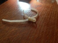
6. One of the pictures shows my hand holding some wiring which has a light and a circle thing (capacitor?). This looks out of place. Is it normal? or has it fallen off something? or has someone done it as a bodge?


Thanks for reading my first post in this thread. I promise to update it as and when I make progress. Please note: My life is chaos and I get barely any time in the week to do anything so most work will be at the weekends.

Cheers,


Johnny

p.s sorry my pictures posted twice, I'm unsure how that happened and am far too tired now to rewrite the thread, it's taken me ages to get this uploaded, so please forgive me.
 
Hi Johhny,

Yes fuse F21 is responsible for the main 50V feed to all the high power coils, so yes, it is as simple as that, with that fuse blown, the game with not kick out balls and not do anything.

Yes, that is a slow blow fuse, yes get some spares, yes try Maplin (though they are not so useful these days so might not have them) If they have 3.15amp that would be fine as that is now a more common value than 3amp.

No it is most likely not an actual coil itself that is the cause, there is a lot of residue on the fuse glass, so this indicates that a short circuit has probably occured.

Yes it might be worth you going through each coil and checking the resistance just to be sure, and it will give you a little experience with the different values of different types of coil.

My "guess" is that something either shorted the 50v to ground (check for loose wires on anything that could have touched a coil lug and any other piece of metal. Or it could be a stuck on drive transistor (well a MOSFET in Sega games, but basically it's function is the same as a transistor found in most other games)

Do you remember anything happening before the failure occurred? Did you hear a bang of a coil powering up when you switched the machine on? When you were playing with the x-wing switch, were you causing the coil to fire repeatedly?

If you have spent some reasonable time inspecting for shorts and you are happy there are none (also measure the resistance between a side rail and one of the coil lugs to make sure there is no short to ground) I would stick another appropriate fuse in and see what happens.

Actually, what you can do is pull off the J8 and J9 connectors from the driver board, and then put the fuse in, power up and check it doesn't blow. If it does not, plug in J8 (with the power off) fire up again, check it doesn't blow and then finally re-connect J9 with the power off and again check that the fuse doesn't blow. This test will give us a better indication of where the fault lies if there is a fault.
 
  • Like
Reactions: jww
Sorry question 5 - no it should not have a connector block, someone has bodged. The coil lug is probably broken hence why they have joined it like that, if it works for now, dont worry about it, long term you probably want a new coil soldered on

question 6 - That's a capacitor and a neon, yes it is normal connected across the motor in sega games
 
  • Like
Reactions: jww
#6 - The disc thingy (you're right, it's a capacitor) is most likely there to soak up radio/line interference from the motor. The lamp (neon) is there as a simple current drain should the motor short-out or overload, e.g., if it were to get stuck. This "trick" is used in model railways (I'm a railway modeller too). Basically if there's a short then the lamp comes on draining nearly all the current and protecting the expensive devices connected to the power. In model railways it's common to use 12V car tail-lights and mount them underneath the layout. When you see your feet being lit up you know something is wrong!

I could of course be talking total cr@p but that's my guess and I've certainly seen this arrangement on other modern pinball machines ;)

Well done starting your shop log BTW! Get stuck in there. Pinball machines are pretty robust. They have to withstand hammering around a rather large steel ball bearing and taking a beating from over enthusiastic men!
 
Hello Luke,

Thanks for your replies, I really appreciate the very detailed responses - cheers! I think I understand most of it too. I'm not an electrician but very keen to learn and have been trying to read up about it.

Here's today's progress and responses to your suggestions and questions:

I went to maplins and didn't find any fuses in the shop, but asked and the man who said they keep them in the back!!! So scored these 3.12Amp 250V slow blow fuses (they call them time delay, which I'm guessing is the same thing as the inner wire inside the fuse looks the same as the others in the machine). Thank you very much for saying 3.1 would be fine as otherwise I wouldve been worried and not bought them. Also picked up a couple of other things which seemed useful for future things (was more thinking my knockout table re: springs and washers, but that's talk for another thread).

IMG_2171.JPG

I've put the new fuse in but have not turned the machine on at all today, more later about that.

To answer your question about did I hear any bangs - the answer is no, nothing. I just noticed one day after I wanted to go into the bios etc and poke around, that it would no longer coin up and eject the ball. Also to your other question, when I was gently investigating the x-wing cannon malfunction previously I never touched it with the power on. I had run the machine diagnostics before and left it running the auto burn in thing, so conceivably it popped when I was out of the room briefly to make a cuppa etc.

I did test all coils, with my multi-meter set to ohms 200, I am no expert but found resistance across all of them, so that's good I think? Did find some random coils, like a williams and a beast iirc etc suggesting repairs in it's previous life.

Here's my multimeter and setting I used:

IMG_2175.jpg

Here are my results anyhow: (p.s my description of what coil is what is going to be like a caveman describing the internet)

left flipper = 5.2
right flipper = 4.9
trough = 5.9
left triangle bumper near front = 10.9
right triangle bumper near front = 10.9
big hole in front of han solo coil = 4.2
4x drop targets = 5.9
north circular bumper = 10.8
west circular bumper = 10.8
east circular bumper = 10.8
south circular bumper = 14.7

and finally there is a coil at the back/bottom of the board where a rail drops vertically the ball into, but I cannot get anywhere near that coil so could not test it.

So, after doing that testing and writing down results, I got my light out and started looking for loose wires as suggested. And I found one, rather I found 3 wires soldered together hanging very close to the leaf switch, by the front right triangle bumper. Looking at the switch stub I could see a silhouette on it, perfectly matching the 3 wires solder shape. Sorry that probably reads like a dogs dinner, I'm trying to say, that those wires solder shaped blob was a perfect match and I had no doubt they came from that switch. Also based on your advice about the coils and a short, I can see a coil on a metal bracket right next to the switch, so I bet that's what's happened.

Using soldering iron, I put a tiny amount of solder on the switch stub, then pressed the existing 3 wire blob back in to place. It was done in a second. I'm crap at soldering but was amazed as it took longer to heat up the iron, than the quick 1 second touch and it was fixed into place.

Here are some pix of that bit:

IMG_2071.jpg IMG_2072.jpg IMG_2073.jpg IMG_2074.jpg
IMG_2174.jpg

I looked over the rest of under the playfield and couldn't see any loose wires or metal things looking out of place so was pretty pleased about that.

I did find 3 plugs, not connected and with no obvious partner. I have no idea about these but did notice them when I got the machine, so have documented them:

IMG_2177.jpg IMG_2178.jpg IMG_2179.jpg

I saw that a plastic part above the front right triangle bumper is broken, so documented to remind me to hunt out a new one:

IMG_2181.jpg

I also remembered that I had noticed in the past and written down that the lights under the left triangle front bumper never lit up in the past. Again, I have not turned the machine on today. I did take the 2 bulbs out and using an old 9v battery touched them to it, and they lit up, proving the bulbs are ok. Documented this so I could remember to examine them again the next time I turn the machine on:

IMG_2182.jpg

Here is a couple of pictures of the x-wing which is not straight, to hopefully show it, and a video I took which I hoped would show (sound) the click of the microswitch under the table when I gently pressed it but unfortunately the mic doesn't pick up the sound:

IMG_2183.jpg IMG_2184.jpg


I found a cracked circular bumper plastic and crushed red plastic nipple, reminder to me to hunt out a new one:

IMG_2185.jpg

I also remembered that on the same first go on the machine that one of the 4 drop target things broke off when I played it and then examining the part saw it had been glued previously :( Mental note for me to find a new one:

IMG_2186.jpg

IMG_2196.jpg

Question - Anyone know what these 6 black circles are on the inside of the table near the back, 3 on each side? I'm curious as they seem to serve no purpose:

IMG_2187.jpg

When taking off the plastic cover on the left front triangle bumper I could see the clear plastic ramp was cracked and further examination found what look to be melted crack repairs further up the same ramp :( So another note for me, to hunt out new ramps:

IMG_2188.jpg

IMG_2189.jpg

When looking in the back box thing that there was a loose wire taped up, which I think came from one of those wide plugs. Have no idea if it's meant to be like that, but guessing not, and no clue what I should do about that:

IMG_2192.jpg

In the same pic I also noticed that where the resisters are, the white backing is discoloured - this doesn't look good and am wondering if it's related to that loose wire.

I can't lift the playfield out, it's too heavy (i'm 9stone!) and I don't even know if you can on this table. I can't get to or see the back bottom of the table under the playfield, I'm wondering if there's bits and pieces, like the missing x-wing laser cannon is back there. This is a note for me to consider in the future. But I did find the following inside the machine from the bits I could reach: (except for the coin box and broken drop target head, that broke off on my first game - grr, and I keep all bits I find in a tub, for easy future reference):

IMG_2195.jpg

IMG_2197.JPG

I did find 2 thin wires that go from back underside of table somewhere up to top box that were not in copex and some empty copex, tied in a crazy manner in the top box, so sorted that out. Sorry, I forgot to photo that, but clearly they were meant to be together to keep the wires catching on the massive dual cannon thing when the playfield is raised.

Ok, last part and perhaps most important. This is why I did not turn it on today and would very much appreciate advice on this. You asked me to test resistance between a coil and the side rails. I'm guessing this is the metal strips running up each long side of the table, so I tested them, no reading on the meter, but there is a reading when I touch from the coil to the front metal bar under the lockbar. This has scared me to death so I did not turn it on, in case this was the real cause of my problems. I made a video of this:


I tested this several times in case I was touching something wrong and got a reading of approx 160 each time. Is this a problem? I'm rather scared about this so will not turn on the machine for fear of hurting it, even with the solder work previously mentioned completed and new fuse installed.

This is also why I have not done your unplugging wires in the top back box tests yet, as it's an unexpected discovery. Sorry if I'm being silly and barking up the wrong tree, but this is my ferrari and I do not want to hurt it.

Ok, that's it for today. I'm exhausted! I also have a lot more respect for those people who create shop logs, as it's taken nearly as long to upload pictures, videos and do this write up as the investigate work today itself!

Have a great evening, I've got a bottle of jedi rum that is calling me :)

Cheers,


Johnny
 
Quick post - just seen your post Nedreud, thank you for explaining that - I was super curious as I was worried it had fallen off of something as couldn't think of a reason to put a light under the playfield. Thank you very much for taking the time to explain it and your encouragement. I've just posted up todays progress as you've no doubt seen by now and am proper tired!

Cheers,


Johnny
 
Just read you post. Looks like you got lots of little niggles to fix! Well done spotting those wires that had dropped off the leaf switch. Could be a likely candidate for causing the short that blew your fuse! You can double check in the manual that that's where they're supposed to go. There should be a wiring diagram telling you which colour wires connect to which parts.

None of those coil readings look way out to me and there's always a little variation. The most comprehensive resource I've found is the Pinball Medic's Electromechanical and Solid State Pinball Solenoid Coil Charts to find what resistances they should be. It's a massive and messy page but the info is in there somewhere! They don't have to be exact but if they're double or triple then something is wrong!
 
  • Like
Reactions: jww
TBH the coil resistances look fine. The wires off the coil leaf switch (which is an End of Stroke or EOS switch) are most likely the culprit for the blown fuse as they will have shorted on the coil mounting plate.

There are always lots of unconnected wires in pinball machines as they tend to be generic wiring looms and if you game doesn't have certain features that other games produced at the same time then they are left unconnected, eg fittings for a shaker motor.

The readings on your meter for coil to lock bar holder show that something is active and making a circuit. I'm guessing it will be a smoothing capacitor or something like that which is connected to earth so personally I would not be too concerned. However the lack of earth from the lock bar to the side rails should be addressed. It could be that the earth is made when the lockbar is in place but there ought to be a wire (or earthing braid) connecting them instead.
 
  • Like
Reactions: jww
Thank you Nedreud for your post and link, I'll be sure to read up about the coils and check the colour of cables to see if I can confirm those wires came from that switch, thank you.

I've put that link and the pinball manual on to my tablet so I can read it on the train tomorrow and will come up with my next stage of testing plans this week coming.

Cheers,

Johnny
 
Thank you Moonraker for your post, I appreciate that. I feel better now about those loose unconnected plugs I found. The generic wiring loom makes sense. It was confusing finding connectors that didn't connect to anything for sure!

I had a very quick look and could see some earth braid? if that's the correct word stapled around the cabinet and it looks like it goes up to that place I was testing and getting some resistance, so have added to my list to further investigate this next. I'll be sure to take pictures and video as well as more multi meter tests. I feel less worried but won't turn the game on again until I can report back and investigate that issue further.

Thanks again.

Cheers,


Johnny
 
No need for me to chime in as everyone has already given great advice. A good read though.

From the sounds and looks of things, that's a decent machine you have there. Those minor issues you have will be fixed in no time I'm sure.
 
  • Like
Reactions: jww
i also agree that this is a good read. those things that Johnny is concerned will make his post seem dreary or somehow bad are actually what brings the post to life, as the vast majority of us think in exactly the same terms as you, and have no idea what we are looking at or looking for. those guys ^ Luke and Peter Nedreud and Peter Moonraker know their stuff. just like you, i see blobs and i see wires and i see round things and i see things that look funny, i don't see capacitors or smoothing currents or any of that malarkey. so your post written in newbie terminology demands an explanation in newbie terminology from those jedi masters, to the benefit of all.

if i can chip in anything helpful i will, but basically just keep doing what you are doing. oh, one thing i can maybe offer is that when you find a popped fuse, yes the solution is to replace it with the correct one (from the manual, not the same as the one that you just removed necessarily) so yes you should get hold of some spares of all the common sizes, but also i've found a brilliant shortcut is to use a thing called a circuitbreaker you can get here: look, click me. basically you put one of them in where the fuse was (you have to get one of the right amperage, so ideally you need to get a selection of sizes) and then when the fuse 'pops' you just reset it instead of having to go through a whole box of fuses. oh, and those things aren't quite the right size, so you have to bend the tabs a little to make it slightly bigger. worth a thought.

keep up the good work. as a reward you get an animated gif of underwater Jessica Alba. i have plenty more of her if you like that. she's pretty special.

gif jessica alba underwater2.gif
 
  • Like
Reactions: jww
Hello friends,

Quick mini weekday update. Fortunately or unfortunately (or both) I have to start work much later tomorrow due to having to go to a customer site out of hours to do use my force powers to sort out some network router.

This means I don't have to go to bed early and can sleep in tomorrow before going up to London and wont get back until gone midnight!

All I was thinking when I learnt this today was 'Oh well, on plus side, I get to push on my training on the ways of the force' :)

Something was bothering me about my testing of the resistance between the coil, side rails and front metal bar that I videoed and uploaded previously. Finally I realised I had made a mistake. When I tested against the side rails and got no resistance (but did against the front metal bar), I realised that when I was touching the multimeter against the side rails, that I was touching painted metal!

Paint doesn't conduct that well, if that's the right word! Doh. So I looked, found some scratched parts of the side rails which exposed bare metal, repeated the test and yes, now I get the same 160 resistance between the coil and the side rails, just like I did between the coil and the front metal bar.

Ok, so if I'm understanding correctly, then the test Luke asked me to do is showing that something is shorting to ground and it's in several places.

I must admit that I don't know where to go from here regarding that problem, but will have a think and keep looking for things that don't look right in the machine.

I downloaded a ton of pinball repair videos to my tablet and watched quite a few on the train today - it's a great way to make 6 hours disappear for sure! I was watching one of Luke's many brilliant videos and saw one where he'd bought a pinball where some crazy fool had cut the earth braid wire in many places. I made a note to check mine as it seemed logical that if mine had cuts/breaks in it, that may be the cause of the issue I found and videoed previously which is in this shop log.

Inspected the insides of my machine tonight and couldn't see any cuts or breaks - so then put my multimeter into continuity mode, tucked one of the terminals under the strip to make contact, then took the other terminal and touched lots of the braid all around the machine. It always beeped, suggesting to me that strip was not broken, at least on the random varied bits I tested. I also touched it against the front metal bar, from the video and it also beeped. Ok, confusing, I was expecting that not to be connected to that earth strip stuff.

Had a think, then looked for the strip on the playfield underside. I couldn't find it, but could see similar but smaller wire under the table, stapled to the wood, connecting up several small groups of components, like light bulbs - so figured this must be earth too - I left one terminal in the inside bottom of the table tucked under the big braid and tried touching the smaller wires under the playfield (that I thought/think are earth things) and got no continuity at all. Confused I tried touching my terminal against anything I could under the playfield and for the life of me could not get a single beep out of my meter.

What I'm trying to say badly is I could not make continuity from inside the bottom of the machine earth braid wire to anything on the underside of the playfield.

So...

Today's main question is - Should there be continuity between that earth strip in the base of the machine, to any part of the underside of the playfield? Because I couldn't find it in tonight's testing to save my life - so just documenting that and wondering. I have no idea if it should be or not, but first hunch was that there should be, since I could test continuity of that earth wire right up to the metal posts in the sides of the machine which the playfield sits on (peg like things) that the playfield rotates on when you elevate it. I could not see this earth wire connected to the playfield at all.

That aside, I found some more things that don't look right, so have taken a few pictures.

1. I found a broken off small piece of wire with 2 colours on it. I will look up in the manual what this is from and see if I can't work out if it's a legacy piece from a previous repair, or if it's from something that is supposed to still be connected

IMG_2203.jpg
2. Looking under the table there is a group of white plastic things, which I believe are part of the tie-fighter matrix lights. Sorry I'm not that accurate, I have a monster headache, am tired and this is slightly overwhelming.

If you look at the pictures the bottom right white plastic mount thing, has a mainly red wire in the slot, but has bare metal exposed sticking out of it. This either used to have another part of wire that's cut/broken off, or it's meant to be like that, or it's a bodge (I think). I think this because looking at all other white plastic terminals, I see no exposed wire sticking out that looks the same as that.

If my pics aren't detailed enough, please let me know and I'll try to take a better pic and video and circle it on my image when I get more time.

IMG_2207.jpg

IMG_2206.jpg

3. Surprised I didn't see this before, but the more time I spend looking, I seem to notice more things. I need to look this up in the manual as I have no idea what the smeg I'm looking at, so those of a sensitive disposition should turn away now...

There's a few black 2-3" tower things under the playfield. One of these has some terminal things with wires pressed in to them. On looking I finally noticed black electrical tape - amazed I didn't spot this before, it's so obvious! Took off the electrical tape which pretty much fell off and saw the wire has been twisted together!!!! I am a dummy but even I know that's not good:

IMG_2204.jpg

IMG_2205.jpg

Head hurting now so time to go to bed. I won't touch this until I can speak to you kind people but I'm thinking I should solder those 2 wires together (they are the same colours completely) and put one of them insulating heat shrink tubes over it, but will read up in the manual what that wire is first and report back when I have time, before doing anything.

Quickly before I go off, just wanted to say:

Thank you to Rus121 and cooldan for your kind words and encouragement. Also thanks to cooldan for the circuitbreaker tip, that makes a lot of sense. I will have a read and order them when I next get time, thank you sir. Also tq for the animated gif, that's brightened up my eyes and evening :) *blush*

Also, a kind person out on the internet posted a comment to my youtube video about the x-wing cannon problem that I posted earlier in this shop log, with some advice, that makes a lot of sense to me, and also has caused me to think that I know what the problem is, or at least, some other things that are wrong with my x-wing and a path to fix it, but I'll elaborate more when I have the time.

Ok, brown-leader heading to bed now :)

Cheers,


Johnny
 
I like to make my wires all nice and straight like, so the heat shrink idea sounds good to me. As long as it does in fact need connecting up and is not some bodge of some sort? Looks ok to do.
 
  • Like
Reactions: jww
Ok, so if I'm understanding correctly, then the test Luke asked me to do is showing that something is shorting to ground and it's in several places.

First off - it only takes one thing to short to earth, this will then be seen on earth's throughout the machine.
Second - You've proved the earth continunity from side rails and lock bar.
Third - as I've previously said the meter reading is not a direct path to earth (shown by the 160 resistance as you put it) and is probably going through a smoothing capacitor, filter or somethng similar which is making the circuit. This is probably normal for that machine. I would be happy to switch the power on. If the fuse blows then you still have a problem somewhere, if it doesn't then you sorted the problem when you soldered the wires back on to the leaf switch.

I must admit that I don't know where to go from here regarding that problem, but will have a think and keep looking for things that don't look right in the machine.

Feel free to dig as deeper hole as you like...!

Inspected the insides of my machine tonight and couldn't see any cuts or breaks - so then put my multimeter into continuity mode, tucked one of the terminals under the strip to make contact, then took the other terminal and touched lots of the braid all around the machine. It always beeped, suggesting to me that strip was not broken, at least on the random varied bits I tested. I also touched it against the front metal bar, from the video and it also beeped. Ok, confusing, I was expecting that not to be connected to that earth strip stuff.

Exactly what you expect with all the earths tied together.

Had a think, then looked for the strip on the playfield underside. I couldn't find it, but could see similar but smaller wire under the table, stapled to the wood, connecting up several small groups of components, like light bulbs - so figured this must be earth too - I left one terminal in the inside bottom of the table tucked under the big braid and tried touching the smaller wires under the playfield (that I thought/think are earth things) and got no continuity at all. Confused I tried touching my terminal against anything I could under the playfield and for the life of me could not get a single beep out of my meter.

What I'm trying to say badly is I could not make continuity from inside the bottom of the machine earth braid wire to anything on the underside of the playfield.

Light bulb braid is not earth so no continunity as you found. If power was applied to the machine you'd be able to measure voltage between the playfield lighting braid and the cabinet earthing braid.

Today's main question is - Should there be continuity between that earth strip in the base of the machine, to any part of the underside of the playfield? Because I couldn't find it in tonight's testing to save my life - so just documenting that and wondering. I have no idea if it should be or not, but first hunch was that there should be, since I could test continuity of that earth wire right up to the metal posts in the sides of the machine which the playfield sits on (peg like things) that the playfield rotates on when you elevate it. I could not see this earth wire connected to the playfield at all.

Depends on the machine and how it was designed at the time. The earthing braid in the cabinet is to project joe public from getting electrocuted, joe public don't touch the playfield (or aren't meant to).

That aside, I found some more things that don't look right, so have taken a few pictures.

1. I found a broken off small piece of wire with 2 colours on it. I will look up in the manual what this is from and see if I can't work out if it's a legacy piece from a previous repair, or if it's from something that is supposed to still be connected

If somethings not working then look there otherwise suspect legacy from previous repair.

2. Looking under the table there is a group of white plastic things, which I believe are part of the tie-fighter matrix lights. Sorry I'm not that accurate, I have a monster headache, am tired and this is slightly overwhelming.

If you look at the pictures the bottom right white plastic mount thing, has a mainly red wire in the slot, but has bare metal exposed sticking out of it. This either used to have another part of wire that's cut/broken off, or it's meant to be like that, or it's a bodge (I think). I think this because looking at all other white plastic terminals, I see no exposed wire sticking out that looks the same as that.

If my pics aren't detailed enough, please let me know and I'll try to take a better pic and video and circle it on my image when I get more time.

As someone has already said just snip off the surplus.

I won't touch this until I can speak to you kind people but I'm thinking I should solder those 2 wires together (they are the same colours completely) and put one of them insulating heat shrink tubes over it, but will read up in the manual what that wire is first and report back when I have time, before doing anything.

Yep, solder and heatshrink if you have some.
 
  • Like
Reactions: jww
Hello Moonraker,

Thank you for your post. Thank you for taking the time to reply with detailed information, I mean it. I’m such a newbie I need and appreciate this guidance. Sorry I misunderstand things.

I’ve been given this book by a friend that I’m trying to read and learn: “Radio Shack - Getting started in electronics, by Forrest M Mims III” which I’ve scanned in to a pdf and put on my tablet. I know I won't instantly know what I'm doing just by reading it, but it's a start.

Sorry if anything I say is stupid.

I’m pleased now that I’ve proved continuity of the earth braid strip in the base of the machine, that’s great news.

When I’m not so broken from real life I will get the video recording and turn on the machine at the weekend and report back.

I did laugh about digging a deeper hole - I think you’re right. I think that I’d rather find problems and then go away and learn how to solve them, than not spot them, but yes, you’re right, I do feel like Alice at the moment!

Thank you for explaining about the non link of earth continuity between the play field and the base of the machine. That answers my question.

I will snip off the surplus on that exposed wire in the tie-fighter matrix lights bit I found, thank you and the others who gave advice on that.

Regarding the twisted together wires, I will solder and heat shrink when I can. I’ve read up the manual a bit more and found 3 places that mention green and white wires, I just want to read more and narrow it down to a single thing before I proceed. I will report back, just want to try to learn myself as that will help me move forward with the whole project.

Thanks once again. Have a great rest of your week Moonraker and other pinballinfo friends.


Cheers,


Johnny
 
Hello again friends,

Ok, quick update. Today I setup the video recording, the fuse F21 had been replaced and the loose wires had been soldered back onto the leaf switch, that's all that has changed.

The other issues I'd left alone reasoning that they'd clearly been there a while and needed a bit more research before attempting to resolve those ones.

Turned it on, ball didn't kick out when pressing start again. Video is below:


I turned it off and checked the top box and F21 had blown again :(

IMG_2221.jpg

The machine does make a little clunk sound when turned on as you may hear in the video. I didn't know if this was normal or not. But thinking back, Luke did ask me if I heard anything blow up ; I didn't previously and didn't think I'd heard such a sound this time either - this could be my poor hearing or lack of experience with a fuse blowing sound - I'm glad I took the video so you can judge for yourself.

Would appreciate feedback on the video my friends. Is the switch-on sound in the video not what I should be hearing? I'm guessing not now, bearing in mind the advice given to me. Sorry, I guess when something blows, I was kinda expecting something louder and or a flash. But clearly something isn't right still because the fuse blew in that 1 min video.

I'm very tired so going to rest up a bit, but will re-read all the advice given and think I'll try the excellent isolating advice that I was given previously and will try unplugging those wires in the top box exactly as directed, when I feel a bit more with it.

Will report back when I can.

Cheers,


Johnny
 
Hello again,

Bit of a sleep works wonders, feel much brighter woo :)

Ok, on to business...

Machine is off. Inserted new fuse F21. Disconnected J8 and J9 wires in the back top box. Powered on the machine. Looked at fuse, looks ok.

Turned machine off, plugged in J8 again, turned on machine, boom, fuse flashes/self-terminates. To be sure, test continuity with multimeter which fails and fuse looks burnt on the inside.

Right, so while nothings solved, do now know it's something connected with J8. So tonight I'll be trying to understand the wiring diagram in the manual.

I haven't tried it with only J9 connected and not J8 (which was to be the next test if J8 didn't blow the fuse) - Is that something I should try even though I know that with J8 only connected, it blows the fuse?

Big thanks to Luke for the advice, this has narrowed things down and I wouldn't have got this far otherwise.

Oh yes, I videoed that whole lot, so if you're interested or can't get to sleep, there's a 6 minute video here:


Cheers,


Johnny
 
Ace! Thank you Moonraker for answering my question.

Today I was making notes re: each wire on the J8 connector, the colours; and then attempting to find where they go in the machine. Have found all bar one ; and it's not where the manual seems to say it is - but I haven't finished yet.

Once that's done I'll cross reference that all go to where the manual says they're supposed to. Then continuity test each to verify. After that test/examine each device on the end of those wires.

Will report back when I can.

Cheers,


Johnny
 
Hi Johnny, sorry I missed this thread earlier, but I'd like to return the favour for checking anything in my SWT - let me know if there's anything you want me to check or test. I'll give the video a watch later too :)

cheers
Graeme.
 
Hi Johnny, sorry I missed this thread earlier, but I'd like to return the favour for checking anything in my SWT - let me know if there's anything you want me to check or test. I'll give the video a watch later too :)

cheers
Graeme.

Hello Graeme and everyone,

Sorry for the late reply and thank you very very much for your kind offer.

Again sorry to you and all that I've gone awol for a while. I'm afraid I let it get to me that both of my pin's were not working and that I hadn't had more than a handful of minutes playtime totalled for both since I bought them due to problems. Investigating the current issue, the short on that line made it more complicated because I'm not strong enough to lift the playfield out, which I need to do, because I can't reach/see all the coils that hang off that connector, not even close. Throw in some real life issues and it became too much for me, so I backed away until I was ready to start again.

But, I'm back. I've got up again and trying not to get down by things. I went out today, found something interesting and will be getting some help with my other pin starting tomorrow. This will lead onto getting some help with SWT afterwards, so probably no updates for a while, but for the first time in a long time, I have some hope and don't feel lost.

I'll create a separate thread about what happened today, just wanted to give an update for you all.

Take care and Cheers,


Johnny
 
As a side note, my SWT started blowing fuse F21 recently too, following a problem with the super VUK. Turns out prior to the fuse going, the problem took out the Q2 transistor so that was constantly locking on and activating the auto launch coil whenever I turned the machine on. Thanks to the diagnostics in the posts above I was able to identify and replace Q2 with one of these IRL540N's from CPC:

http://cpc.farnell.com/internationa...sfet-n-100v-36a-to-220/dp/SC11124?Ntt=irl540n

One thing that might help is page 88 of the manual which has the list of coils that are attached to J8. Some of these can be disconnected to isolate which area might be broken.

cheers
Graeme
 
Hello Graeme,

Sorry for the late reply, I completely missed it!

Oh wow, that's ace, thank you kindly for the advice.

Mine is still untouched, I had spoken with a local SS pinball fixer expert and had been waiting for him to get back to me when he's ready. I put off chasing him as xmas is a crazy time for all, but I'll drop him a line. If he's no longer available I think I'll have a go at your advice above as I understand enough of that (i'm really new to this), to have a go safely and slowly.

Thanks again. I'm constantly amazed at how brilliant, helpful and nice this forum is.

Take it easy,

Johnny
 
Hi Paul,

Heh ace - well keep it up sir! (No laughing at the back Mr Dan :)

I get nervous chasing people and don't like it because I get chased all day at work and then outside work by family and friends, so I don't want to do it to others, but I think it's been long enough so I've sent the pinball fixer a very nice friendly email asking if he still wants to fix my machine. If he doesn't, no hard feelings etc, but I'll then have a look at it myself again - or ask about if there's anyone else local.

I simply must get this fixed soon. I've barely had a handful of games on it before it self-terminated and I really just want to play on it!

Will keep you all updated.

Thanks again.

Cheers,

Johnny
 
Man....this is the most polite....eloquent....clear n descriptive ..... Shop log EVER ........
Dont make your fault finding too difficult, it is usually something basic and easy to remedy . You'll kick yourself once it is found. Always revert to basics....it works for me.
There maybe someone near Deal who could pop round n scope it out for you......
 
  • Like
Reactions: jww
Thanks for your kind words pintableuser, I appreciate that friend :)

Status Update as it's been a while:

Ok, I'm going to give up waiting for the local pinball repair man. No bad feelings, but it's been a long time since I first contacted him and have very politely chased a couple of times, to be told he's extremely busy but will still get to me. I only live a very short distance away, have had no initial examination visit, so am concluding that he'll never get to me, so I'll no longer be contacting him or waiting for his services. Again, to be clear, no hard feelings at all, but I can't stay in limbo.


Now to decide what to do. I'll probably have a go at Graeme's suggestions, but I only understand part of what was said, so will re-read and go off an investigate. I'll post my method before I touch anything, once I've had chance to read, re-read, compare with manual and have a think.

Cheers,


Johnny
 

Attachments

  • IMG_0612.jpg
    IMG_0612.jpg
    126.2 KB · Views: 7
Back
Top Bottom