Hi,
Some of you will already know that I just got my first Pinball Machine, Time Machine (Data East). Unfortunately things have not gone well right from the start, see my post in the General Pinball Discussion Thread " My experience owning my First Pinball Machine (unfortunately things have not been so great so far)
A damaged Pop Bumper has ultimately led to a burnt out Coil and likely shorted Transistors.
I will update here as and when on what I find, if anyone can chip in and help and offer some guidance that would be very much appreciated.
**Updated 14:43 Sunday 19th December 2021**
PSU BOARD
First Checks - Fuse F5 is blown (fitted was a 4A, manual States 3A)
Seconds Checks - All Pop Bumpers and Slingshots are common and share the same Supply from 9-Way Connector (CN3) No visual faults seen on the Connector.
PLAYFIELD - SOLENOIDS (bumpers and slingshots)
SP4 (RED) LEFT POP BUMPER (DRIVE TRANSISTOR Q11)
Coil resistance measured: 0.5 Ohms (Coil paper is brown and low resistance confirms the Coil is shorted)
SP2 (YELLOW) CENTER POP BUMPER (DRIVE TRANSISTOR Q9)
Coil Coil resistance measured: 3.7 Ohms
SP1 (BLUE) RIGHT POP BUMPER (DRIVE TRANSISTOR Q8)
Coil Coil resistance measured: 3.7 Ohms
SP3 LEFT SLINGSHOT (DRIVE TRANSISTOR Q10)
Coil Coil resistance measured: 3.8 Ohms
SP5 RIGHT SLINGSHOT (DRIVE TRANSISTOR Q12)
Coil Coil resistance measured: 4.0 Ohms
CPU BOARD
Solenoids are driven by the CPU Board on Connector (CN19)
Visually there signs of a small burn marks around Pin 3 & 4 on the connector body, the connector, cabling and board in this area are all good, I don’t expect there to be an issue with the connector itself.
Visual inspection carried out around the x5 Driver Transistors Q8, 9, 10, 11 & 12 there are no apparent signs of any damage to or around this area, this is good news.
Transistors (Special Coil) - Q8, 9, 10, 11, & 12 are all shorted out, confirmed the Collector is shorted to Ground. (Transistor Types TIP122 fitted)
Transistors (Constant Power Transistors) - Q, 24, 25, 26, 27 & 30 are all shorted out , confirmed Collector is shorted to Ground (Transistor Types TIP122 fitted) No visible damage in or around this area and Connector (CN12)
Based on the above so far the following parts are currently required. All parts will be ordered from Pinball Heaven, I currently have an order in for some items but I want to capture everything just to sure. If anyone can verify and check that I have listed and identified the correct parts or I am missing anything etc etc I would appreciate any support, thanks.
Required Parts,
X1 Solenoid Coil 23-800 Coil (I’ll get a spare also)

 www.pinball.co.uk
X10 TIP122 Transistors (I’ll order plenty additional also) ** TIP102 is a compatible Transistor **
 www.pinball.co.uk
X1 Older Style pop bumper body (I’ll order half a dozen of these, they are cheap)
 www.pinball.co.uk
X1 3A Fuse required for PSU Board F5 (I’ll order a pack, as well as 5A and 8A, for spares and any issues later)
 www.pinball.co.uk
X10 2N4401 Pre-Driver Transistors (I have not tested these as but I will a good few of these just incase)
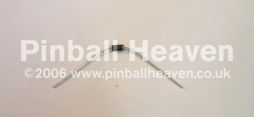
X5 Inline Diodes for the Solenoids/Coils (I haven’t tested these as yet, I’ll order plenty of these just incase , is this the correct type ?)
I need to remove the CPU Board to carry out further checks, but I am hoping the above replacements are correct ?
I also need to look at what’s required for the Pop Bumper, but I guess I should order a good few spares for it and tidy up the other bumpers also. I likely need some support with this, what parts do you recommend I buy and replace on the Pop Bumpers. Again I have not looked at them in detail yet, hopefully later today.
Ideally I want all parts to be ordered tonight/tomorrow with Pinball Heaven, I don’t want to find out later its all stop on a repair whilst awaiting parts that actually only cost pennies.
Thanks for all your help and feedback so far folks, very very much appreciated.


Some of you will already know that I just got my first Pinball Machine, Time Machine (Data East). Unfortunately things have not gone well right from the start, see my post in the General Pinball Discussion Thread " My experience owning my First Pinball Machine (unfortunately things have not been so great so far)
A damaged Pop Bumper has ultimately led to a burnt out Coil and likely shorted Transistors.
I will update here as and when on what I find, if anyone can chip in and help and offer some guidance that would be very much appreciated.
**Updated 14:43 Sunday 19th December 2021**
PSU BOARD
First Checks - Fuse F5 is blown (fitted was a 4A, manual States 3A)
Seconds Checks - All Pop Bumpers and Slingshots are common and share the same Supply from 9-Way Connector (CN3) No visual faults seen on the Connector.
PLAYFIELD - SOLENOIDS (bumpers and slingshots)
SP4 (RED) LEFT POP BUMPER (DRIVE TRANSISTOR Q11)
Coil resistance measured: 0.5 Ohms (Coil paper is brown and low resistance confirms the Coil is shorted)
SP2 (YELLOW) CENTER POP BUMPER (DRIVE TRANSISTOR Q9)
Coil Coil resistance measured: 3.7 Ohms
SP1 (BLUE) RIGHT POP BUMPER (DRIVE TRANSISTOR Q8)
Coil Coil resistance measured: 3.7 Ohms
SP3 LEFT SLINGSHOT (DRIVE TRANSISTOR Q10)
Coil Coil resistance measured: 3.8 Ohms
SP5 RIGHT SLINGSHOT (DRIVE TRANSISTOR Q12)
Coil Coil resistance measured: 4.0 Ohms
CPU BOARD
Solenoids are driven by the CPU Board on Connector (CN19)
Visually there signs of a small burn marks around Pin 3 & 4 on the connector body, the connector, cabling and board in this area are all good, I don’t expect there to be an issue with the connector itself.
Visual inspection carried out around the x5 Driver Transistors Q8, 9, 10, 11 & 12 there are no apparent signs of any damage to or around this area, this is good news.
Transistors (Special Coil) - Q8, 9, 10, 11, & 12 are all shorted out, confirmed the Collector is shorted to Ground. (Transistor Types TIP122 fitted)
Transistors (Constant Power Transistors) - Q, 24, 25, 26, 27 & 30 are all shorted out , confirmed Collector is shorted to Ground (Transistor Types TIP122 fitted) No visible damage in or around this area and Connector (CN12)
Based on the above so far the following parts are currently required. All parts will be ordered from Pinball Heaven, I currently have an order in for some items but I want to capture everything just to sure. If anyone can verify and check that I have listed and identified the correct parts or I am missing anything etc etc I would appreciate any support, thanks.
Required Parts,
X1 Solenoid Coil 23-800 Coil (I’ll get a spare also)
Stern 23-800 solenoid coil P/N 090-5001-ND - Pinball Heaven
Stern Pinball 23-800 coil. Part number 090-5001-ND Also used on Data East and Sega pinball machines but with added 1N4007 diode (available separately on site).
www.pinball.co.uk
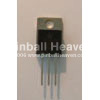
X10 TIP122 Transistors (I’ll order plenty additional also) ** TIP102 is a compatible Transistor **
Medium duty power transistor TIP122 - Pinball Heaven
ORDER TIP102, TIP122 discontinued, pin for pin compatible.
www.pinball.co.uk
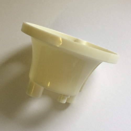
X1 Older Style pop bumper body (I’ll order half a dozen of these, they are cheap)
Older style pop bumper body C-114-3 - Pinball Heaven
Jet bumper plastic housing for older pinball machines Bally Williams Gottlieb Stern
www.pinball.co.uk
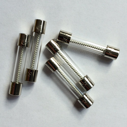
X1 3A Fuse required for PSU Board F5 (I’ll order a pack, as well as 5A and 8A, for spares and any issues later)
32mm Slow blow (1.25") fuse. - Pinball Heaven
Slow blow 1 1/4″ fuses, most sold in packs of 5 but some sold individually (specified on drop down box).
www.pinball.co.uk
X10 2N4401 Pre-Driver Transistors (I have not tested these as but I will a good few of these just incase)
X5 Inline Diodes for the Solenoids/Coils (I haven’t tested these as yet, I’ll order plenty of these just incase , is this the correct type ?)
I need to remove the CPU Board to carry out further checks, but I am hoping the above replacements are correct ?
I also need to look at what’s required for the Pop Bumper, but I guess I should order a good few spares for it and tidy up the other bumpers also. I likely need some support with this, what parts do you recommend I buy and replace on the Pop Bumpers. Again I have not looked at them in detail yet, hopefully later today.
Ideally I want all parts to be ordered tonight/tomorrow with Pinball Heaven, I don’t want to find out later its all stop on a repair whilst awaiting parts that actually only cost pennies.
Thanks for all your help and feedback so far folks, very very much appreciated.
Last edited:


")


