OK Guys promised a brief write up of the Blynk app and arduino control box I designed for my shed, so here it is.
NOTE - this is pretty much a direct lift of a write up I did for the Blynk community website, so rather than reinventing the wheel .......
OK Guys, been a while since I started this and now the project is finished so I am going to share a write up with you all.
The project set out to control two way lighting for my shed build. One switch for the two circuit is virtual via the Blynk app screens, and the other switch is a physical wall switch. The key to the early design was getting the physical switch to feedback to the Blynk app so the widget updated it’s status. This was achieved. Also all of the light circuits are controlled via Alexa using IFFFT as well - very handy!!
The app has further been developed and also controls the heating in the shed and a sauna in the corner of the it, so I wll split the write up into two halves.
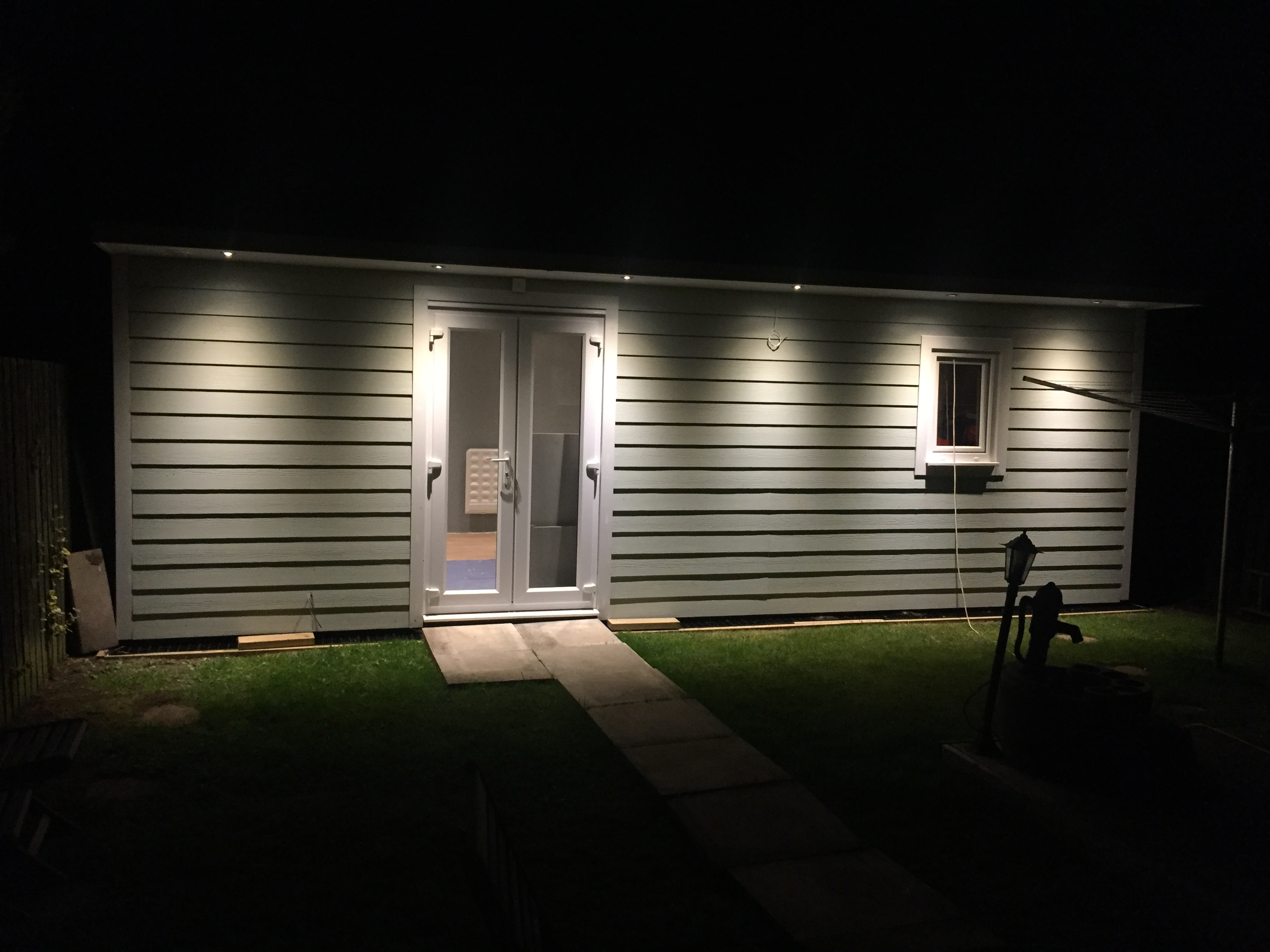
Firstly about the shed. It is my pinball playroom(which has sauna in corner) and a pinball workshop, so essentially split into two rooms.
Here is a pic of it complete - I designed and built the whole thing from scratch myself.

IMG_2329.JPG3264x2448 1.34 MB
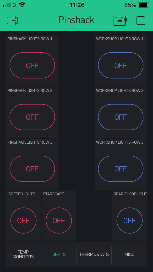
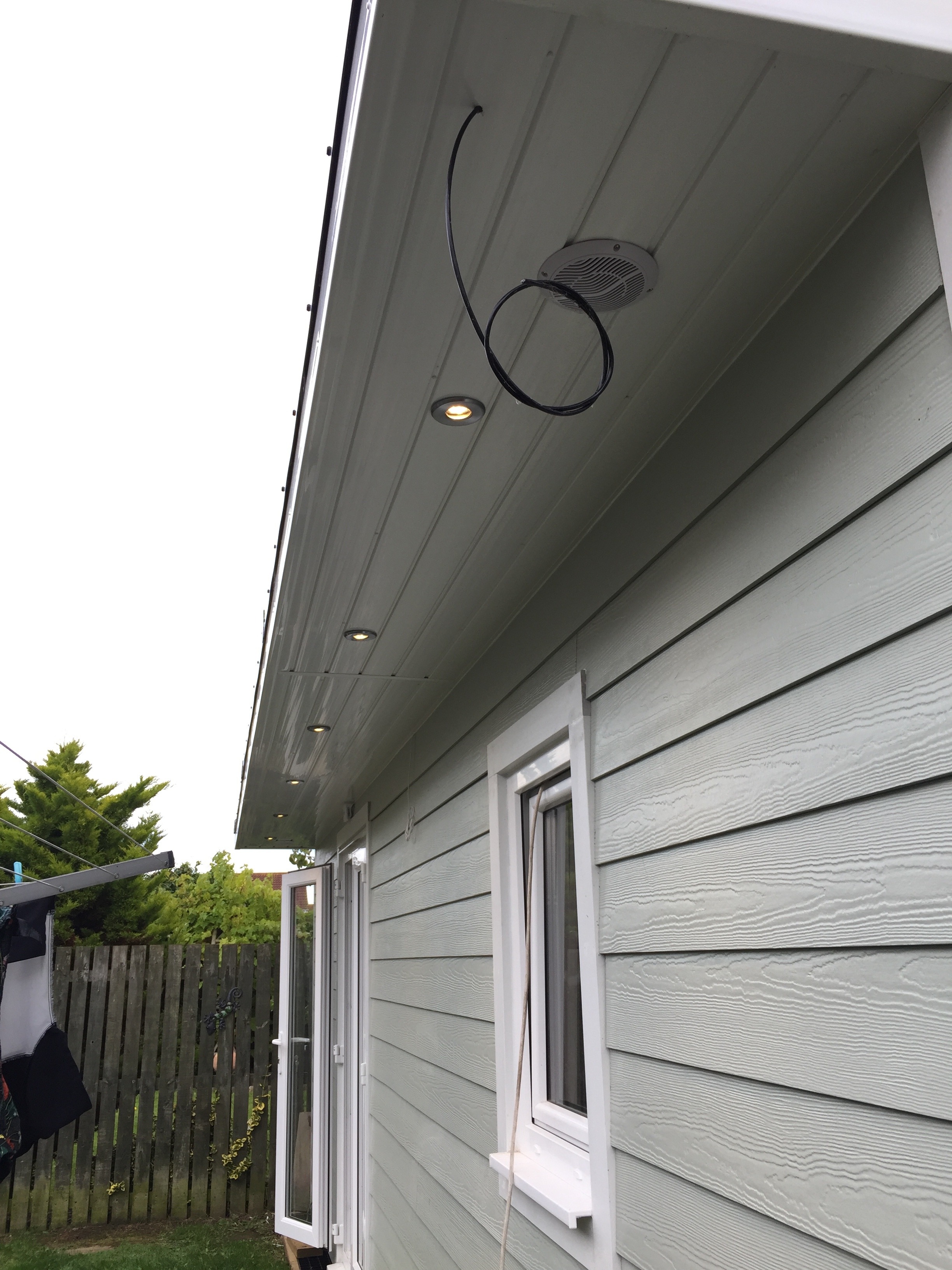
So to the lighting control then. The pinroom has 5 circuits in it arranged in 3 rows of individually controlled downlighters in each row, an outside set of 6 downlighters(on one circuit) in the soffit, and a centre starscape display which is yet to be completed.
The workshop has 4 circuits, again 3 rows of individually controlled downlighters and an external LED floodlight behind the shed for security.
Here is the Blynk control panel for these - red widgets for pinroom - blue for workshop…

IMG_4304.PNG640x1136 56.8 KB
![IMG_4305|281x500]
(upload://9flRy6CB6B5frUuSzbDRrm9Lxsr.png)
You will note in the 2nd screen shot there is another button that appears when you slide the screen up - Emergency button - this switches all 9 lighting circuits on (or off) at once. Useful if I hear noises in the garden.
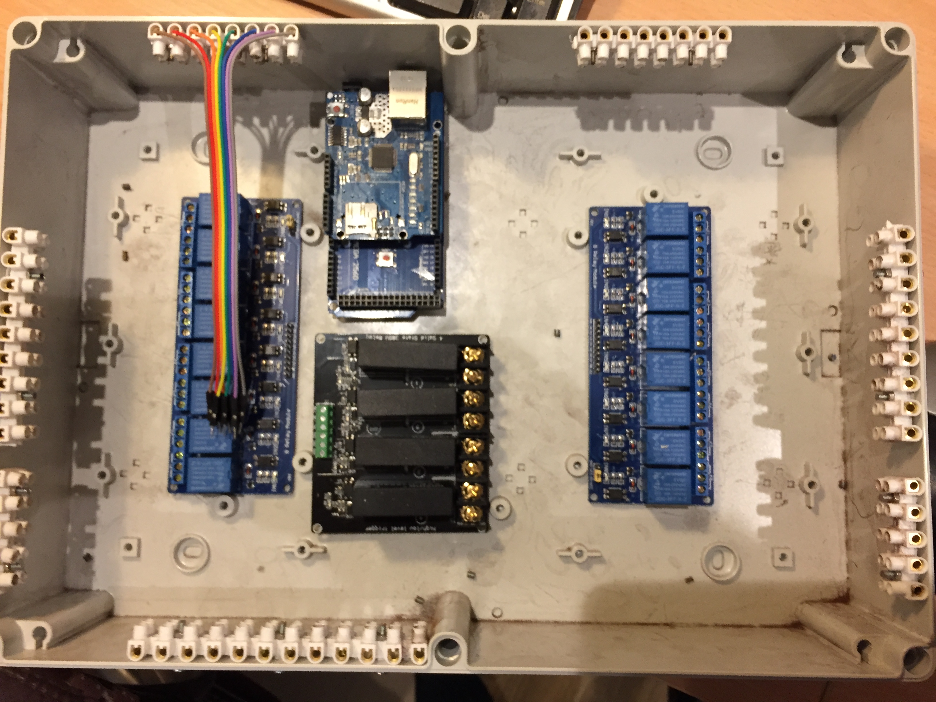
The blynk app controls an Arduino Mega linked to 2 banks of 8ch relays shown below

IMG_2564.JPG3264x2448 1.83 MB
You can see these laid out in the pic pre wiring done. The black SSR relays in the middle were for the heating but proved useles so were replaced with 30A mechanical relays(in shot below) - more on this later.
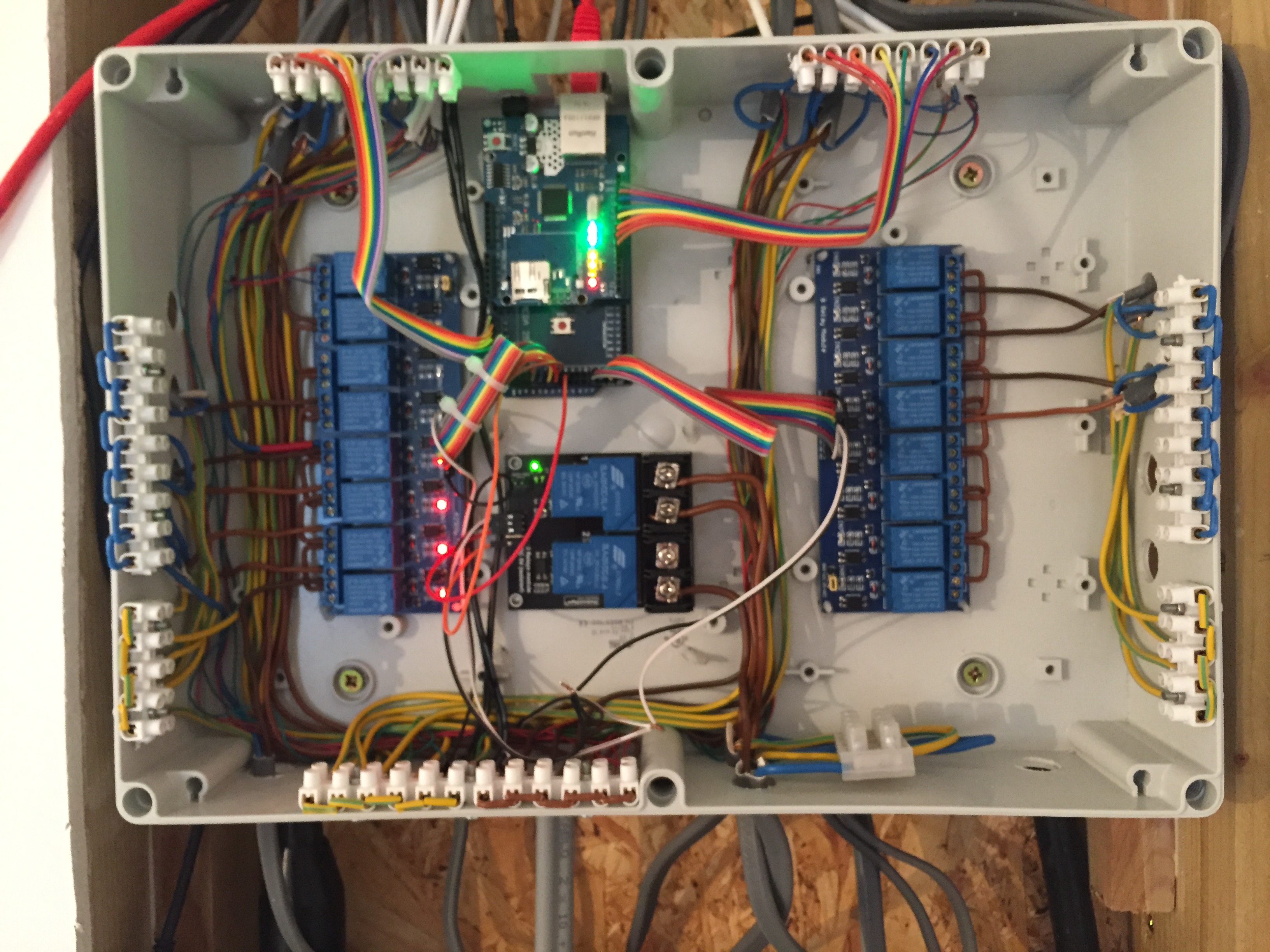
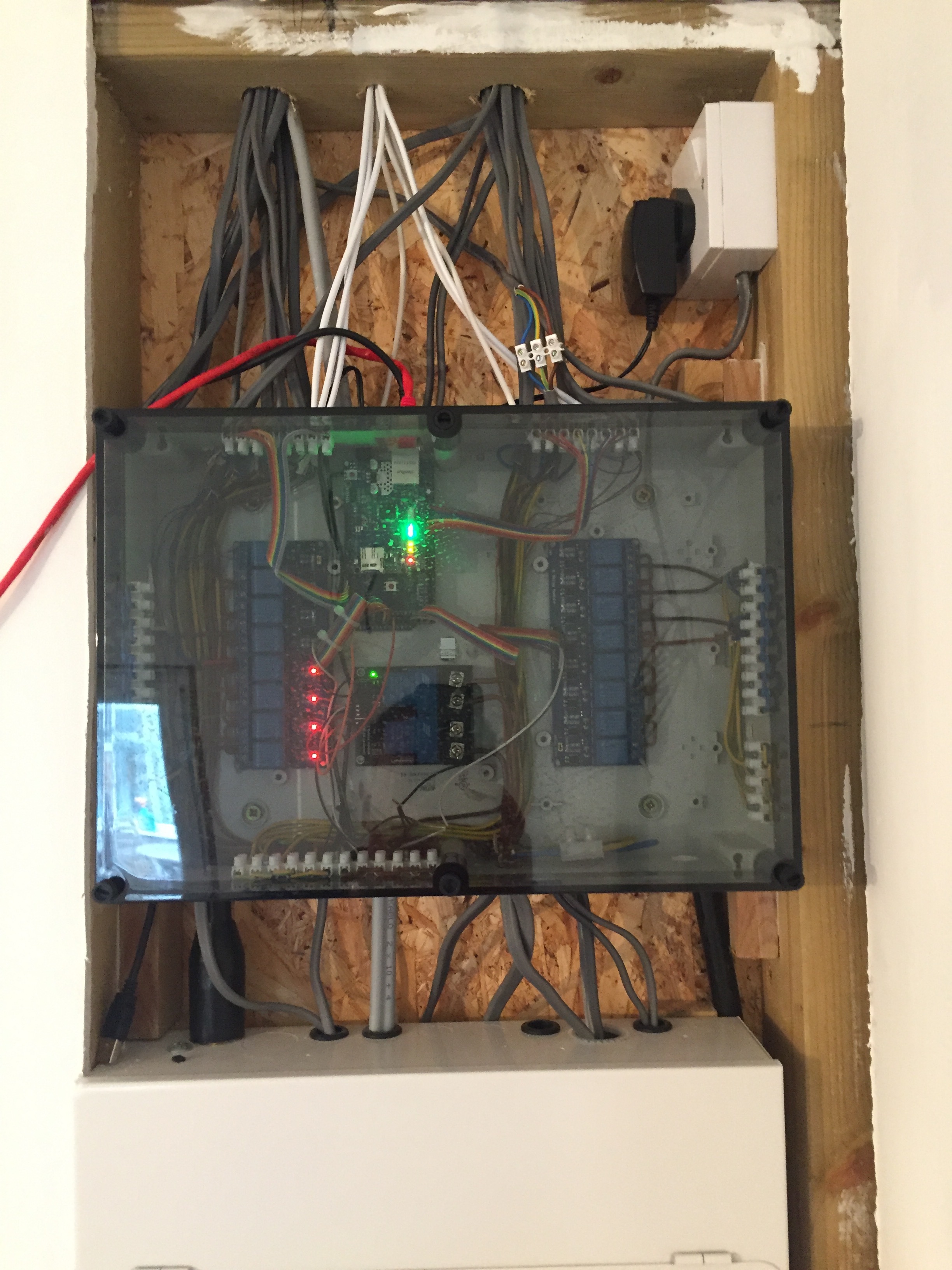
here are a few pics of it now fully loaded. The left set of relays is for the pinroom 5 lighting circuits and 1 for sauna on/off. Right set of relays for workshop 4 lighting circuits. You will note 4 relays are free in the workshop side for future devlopments and 2 in the pinroom side.

IMG_2927.JPG3264x2448 1.39 MB

IMG_2928.JPG2448x3264 1.3 MB

IMG_2999.JPG2448x3264 1.13 MB
The lighting circuits to the physical switches are low voltage connected directly to an Arduino input pin. The physical switches either pulls the relevant pin up to +5v or down to Gnd. These input cables come in the top of the box in the pics via the connector strips.
The power goes out through the left side of the box for pinroom and through right for the workshop(via each relay output). you can also see on each side of the box a row of neutral and Earth connectors for each circuit, and at the bottom a +5v and Gnd busbars(connectors) for the switch inputs.
Reason there are two sets of neutral and earths, is because each set of relays has its own MCB in the distribution board, and it is easy and neater for the wiring.
So the arduino software for this. Its quite simple but there is a lot of it as mutilplied up by the number of circuits. Each arduino input pin(physical switch) is monitored for a change of state and simply switches on the appropriate relay and updates the widget on the app. Similarily a press of the blynk app widget button does the same, ie changes the state of the switch to the opposite it was.
The software is reasonable clever protecting the states of the widgets in case of power loss. The software uses a lot of virtual pins to store the states of them and in the vent the power is lost it reinstates the state of each output/switch widget whenh the power is restored.
You will need to look through the software listing to understand all of this(ask if you want it - its big!!).
Ok I think for the first half that is it. I will do another for the heating control separately.
Please feel free to ask any questions.
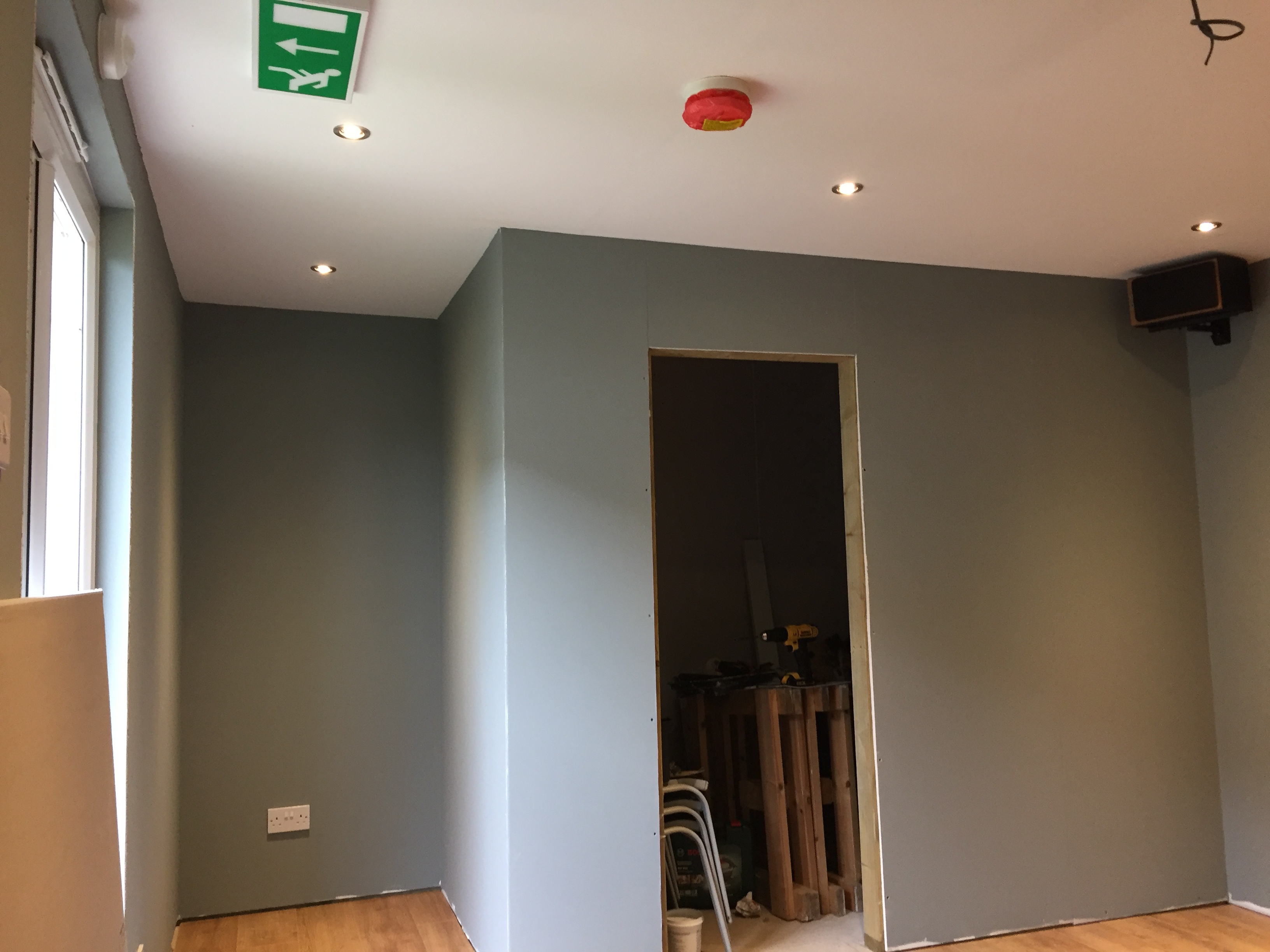
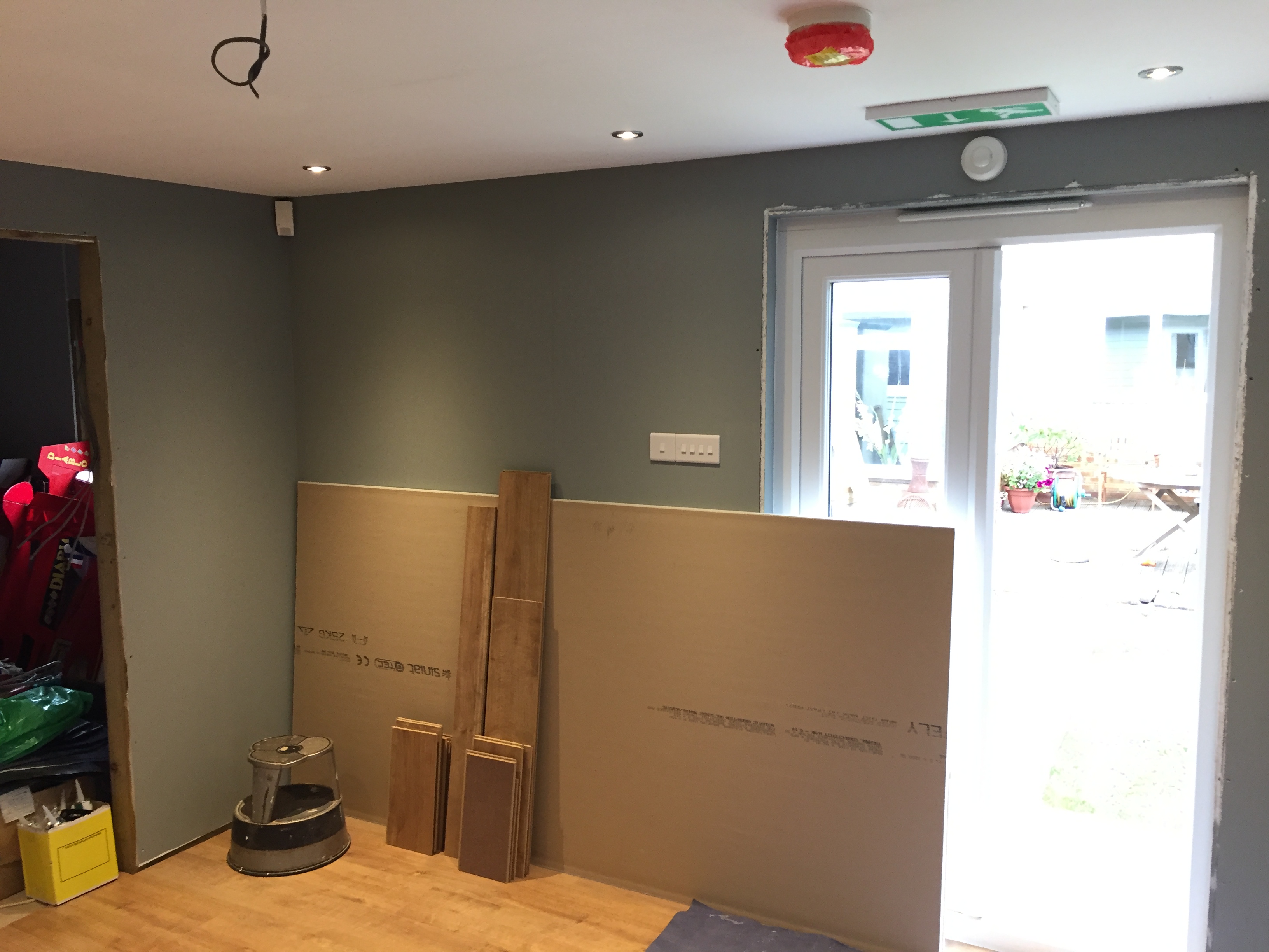
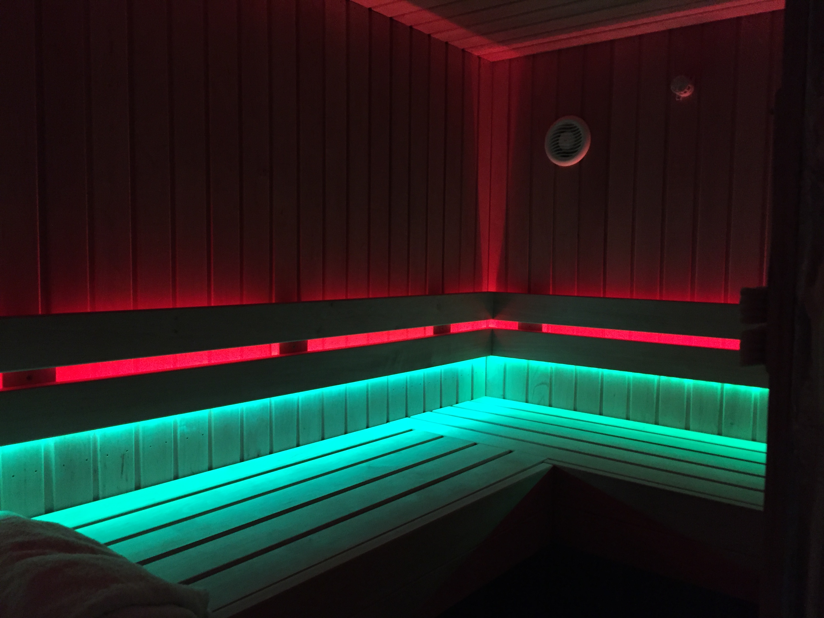
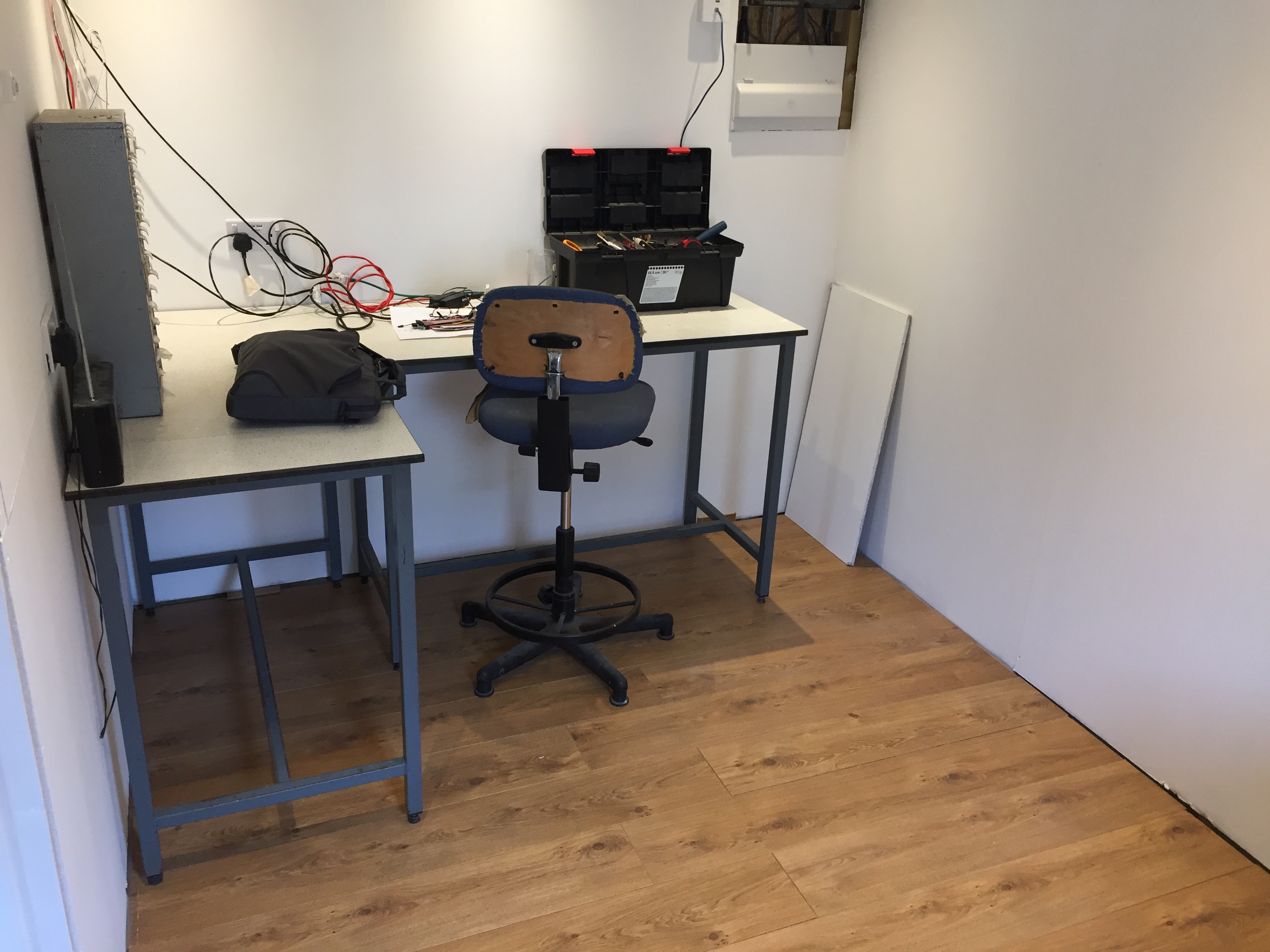
Here are few pics of the rooms within the shed for clarity. Pinroom(note wall switches in some shots) Sauna and workshop and finshed control box above dis board

IMG_2323.JPG3264x2448 1.41 MB

IMG_2324.JPG3264x2448 1.29 MB

IMG_2325.JPG3264x2448 1.29 MB

IMG_2326.JPG2448x3264 1.81 MB

IMG_2688.JPG2448x3264 1.14 MB

IMG_2739.JPG3264x2448 984 KB

IMG_2952.JPG3264x2448 1.53 MB
IMG_2999.JPG2448x3264 1.13 MB
OK So now for part two the heating control for the two room sin the shed via the Blynk app.
Each room has a 1.5kw oil filled radiator in it(see pic in part 1), a DHT22 temp and hunmidty sensor and a PIR occupancy detector. THere is also an externaL DHT22 mounted externally to monitor outside temp and humidity as well. Each of the radiators is controlled by a 30A mechanical relay which can be seen in the centre of the control box - the board with two of them on.
The blynk app displays temp and humidty in each room and outside. It also shows todays runtime for the heating, and yesterdays runtime, and the current status of the heating ie on or off.
This is all shown in the first screen below.

IMG_4303.PNG640x1136 61.7 KB
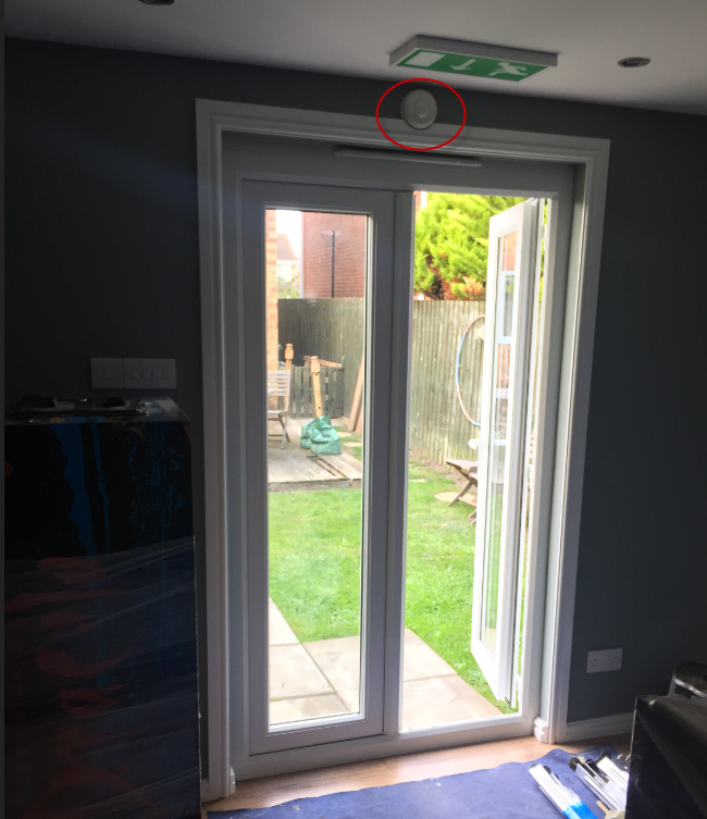
The clever bit of this is the occupancy control. On the next screen are the thermostat settings for each room. There are two sliders per heater- one to set the desired temp and one for the away temp. The software works by sensing if there is anyone present in the room via the PIR occupancy sensor(shown below red circle)

image.jpg650x753 154 KB
Here is the blynk screen for this…

IMG_4306.PNG640x1136 53.5 KB
Blynk will set the temp back to the away temp when no movement is detected in each of the rooms for one hour, and inversley it remembers the required temp for each room, so as someone enters the room it will automatically turn the heating back up to the required temp, set originally by the temp slider.
ie room set to 20c away temp set to 15c, after 1 hour of inactivity pinshack temp slider will drop back to what the away temp slider says, ie 15c, and if someone re-enters the room the pinshack temp slider will jump back up to 20c heating the room.
The principal behind this is to save energy when you leave the room, and to turn heating off or down if you forget to do it yourself. It also gives a constant background temp(away temp) to keep the rooms stable. Of course if you don’t want to wait until you enter the room to heat it up you can just move the temp slider up to what you want to preheat the room, but if you dont enter within the hour it will go back to the away temp!
This works a treat and has proved economical
Also on the temp screen I record and display the Max and Min temps for each DHT22 sensor (ignore the slider for my lounge light!! thats another project)
Finally I have another screen that displays stats and has a hidden slide up again to be abel to reset various values.
Here is the screen…

IMG_4307.PNG640x1136 83.3 KB
So on this screen I have a grpah that displays on it, Pinshack temp and Hunmidity, Outside temp and Workshop temp.
The widgets underneath show electricity consumption per room and a total. So we have KwH of elec used per room, Todays elec cost per room, Yesterdays cost per room, Each rooms total cost since last reset and finally the total cost to heat the whole shed.
All of these stats can be indivdually reset by sliding up this screen to reveal the buttons shown below…

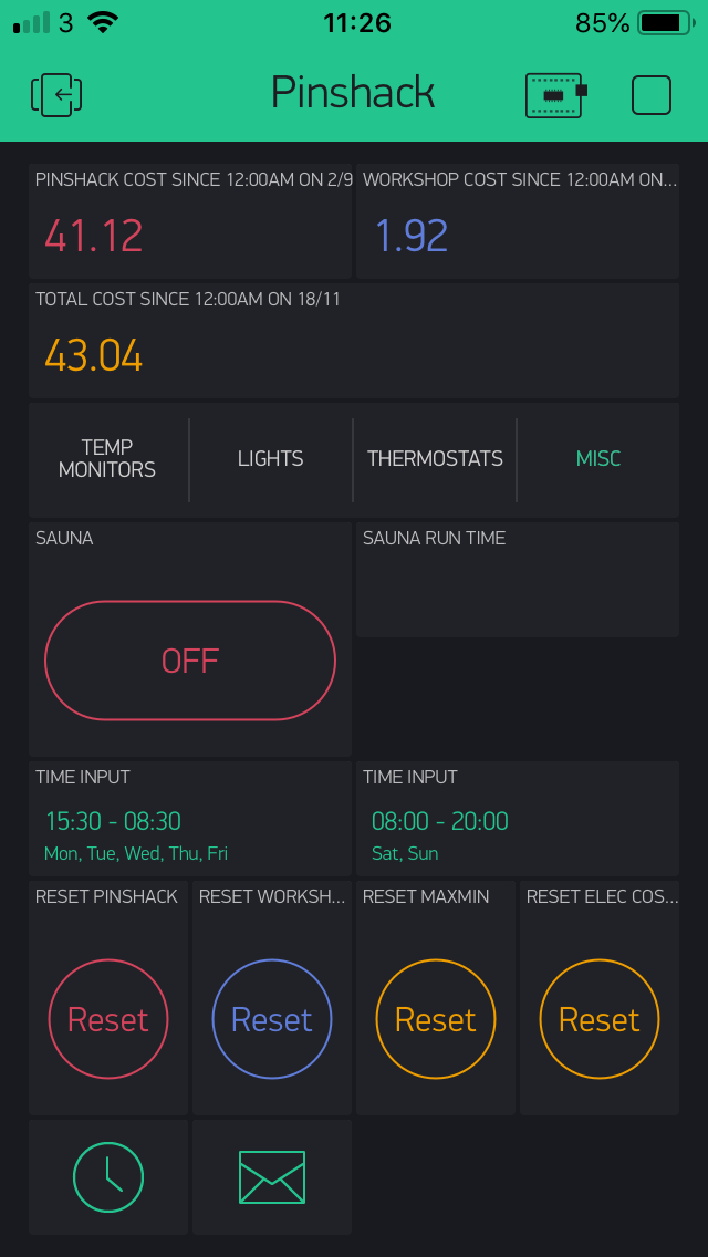
IMG_4308.PNG640x1136 55.7 KB
On here I also have the ability to remotely switch the sauna on and display it’s on time(runtime).
I have widgets to reset pinshack runtime stats, workshop runtime stats, maxmin temps reset and finally a button to reset all the elec stats back to zero. I also have hidden the email and timer widgets here as well.
Thats it !!!
For those interested here is a pinout spreadsheet for all the inputs and outputs to Arduino Mega.

image.png1069x1138 74.9 KB
Any questions feel free to ask
So that's it , you will be pleased to hear, no more from me on this project as now complete(unless you ask of course )
Cheers
kev


")
![IMG_2996[1].JPG](https://www.pinballinfo.com/community/data/attachments/69/69646-1f7ae1a803787af66a538d3834ded9c0.jpg?hash=H3rhqAN4ev "IMG_2996[1].JPG")
![IMG_2999[1].JPG](https://www.pinballinfo.com/community/data/attachments/69/69647-e580c98ab3ceb526a369a5e5caf59529.jpg?hash=5YDJirPOtS "IMG_2999[1].JPG")
![IMG_4262[1].JPG](https://www.pinballinfo.com/community/data/attachments/75/75484-7df7d209df8349335df68f71aeff0979.jpg?hash=fffSCd-DST "IMG_4262[1].JPG")
![IMG_4282[1].JPG](https://www.pinballinfo.com/community/data/attachments/75/75485-7321f050b66e3482f0712ca5788c88a8.jpg?hash=cyHwULZuNI "IMG_4282[1].JPG")
![IMG_4285[1].JPG](https://www.pinballinfo.com/community/data/attachments/75/75486-caba0244663aff7eaccc4715acb7851b.jpg?hash=yroCRGY6_3 "IMG_4285[1].JPG")