What's new
Pinball info

Register a free account today to become a member! Once signed in, you'll be able to participate on this site by adding your own topics and posts, as well as connect with other members through your own private inbox!

Complete Pinbot mini shop log

So, I ran more tests and was happy to put back in the machine. The good news is it now boots, I get it to attract mode and it shows 4 default high scores to date as well as other messages. Looks good.
Lamps are coming on and look like they are in attract mode type of patterns - cant tell if they are right or wrong yet.
No sound - just a horrid hum.
The mechanism in the middle opens and closes - seems to be part of the startup of the machine?


Only the top 4 score displays are working - the bottom one - the smaller one is not lit at all.

I tried to start a game - it says its looking for a ball. 3 balls in the trough. Wont start a game, after a few seconds reverts to attract mode. Not looked under the apron, but looks like optos to detect the trough balls. Needs a closer look.

One time I did somehow get a game started. Flippers worked. The left slingshot switches, instead of firing the slingshot solenoid - they fired one of the pop bumpers. the right slingshot fired one of the other pop bumpers!!!
So, something wrong there - any ideas folks?

I am unfamiliar with williams games of this era, this is my first - trying to get into the test menu - 3 switches in the cab to left side just inside coin door. Advance and an Auto/Manual switch, and a third one. I cannot get them to do anything!

Checked the wiring they are wired back into the CPU board ok. Any ideas?

All the jumper plugs are in the right places, all plugged in ok. Wondering if we have yet more batter damage issues.

Pleased I've got it booting up though!
 
Spent some time tonight tracing back the circuits to figure out why the sling shots are triggering the upper and lower pop bumpers.

i’ve made a good discovery. the slingshot is connected to the same pia as the pop bumper it triggers. each slingshot and pop bumper combo are on separate pia chips so that rules out faulty pia. the commonality is that they both run off the ca2 or cb2 signals. so it looks like the a/b switching logic circuit is faulty.

i’ll look at that tomoz.

[mention]chillpin [/mention] - here is my sys 11 issues


Sent from my iPhone using Tapatalk
 
So, took the apron off - can see a board with 4 leds on it. Don't know what the first one does, it's lit all the time. The other 3 are leds that tell you the status of the 3 trough optos - nice Idea. I put in 1,2, 3 balls to the trough and sure enough these light up correspondingly, so I know the optos are working.

But the CPU isn't seeing these hence cant find the balls and start a game. Could just be a classic switch matrix problem, OR; This possibly ties into the slingshot and pop bumper problem - the A or B part of the PIA chip. So back to that:

I traced all the circuits back - The left slingshot controlled off PIA U38 pin CB2 , the pop bumper it triggers is PIA U38 Pin CA2, and right slingshot off PIA 54 pin CB2 with the pop bumper it triggers is PIA U54 Pin CA2
The switch matrix also uses the A and B circuits- so if A/B wasn't switching on properly - it would fail to read the switches properly. Having said that the Start button works ok and thats on the sw matrix.
Another possibility if there is a sw matrix problem - i.e slingshot switch registering as a pop bumper switch - but it just seems so coincidental that these are on the same pia's and the only difference is the CA2 or CB2 lines.

I've then traced the Register select circuits - R0/R1 - these select the A or B circuit. Come from the CPU chip A0 and A1 adress lines then via U11 - Probed that then got the oscilloscope on it. U11 looks ok - its output is a bit less 'clean' than the CPU inputs, but there again it's a line driver. I would expect it to be really nice and clean on off signals. I compared it to U13 -which doesn't switch at same frequency, but is nice n clean signals, could this be it faulty U11? or maybe an issue with the traces between the U11 outputs 14, 16 and the 3 PIA chips, or maybe a bad PIA chip causing issues on these 2 lines? What to try next? Replace U14 - I'll ordered some? I could also replace U38 and U54 too?

Turning into a right old nightmare is this.
 
Alan,

Apologies if I'm pitching too low, but are you aware that Williams games up to mid 11B have what were called 'Special' solenoids?. The slingshots and jet bumpers had non-matrix 'Special' switches which operated the solenoid without reference to the cpu - it only found about them afterwards, from matrix switches operated by the linkages. Though the Spaniards may not have followed suit, of course. The six Special drives, Special switch connector and the flipper relay are up in the top right of the cpu board. The entire section is enabled/disabled by one line, the name of which I can't recall. With this active (it's a Low, I think), the relay energises, and the bumper/slingshot switches are then able to control the solenoid transistors using some 74## SSI logic gates. In tilt or Game Over, the line changes state and the whole section shuts off. Mostly, in the case of Pin-Bot. When the visor opens in Attract mode, the two 'eye socket' flashbulbs operate. Because one of them is the spare special drive, the line, relay and specials become active. As I realised when a bumper nipped me while cleaning the playfield.

The three switches on that bracket inside the door. One, the H/Score Reset, is just a matrix switch, No. 08. The other two are the crucial ones. Advance controls a cpu line to get into either Bookkeeping/Adjustment or Tests, depending on the state of Up/Down. Up for the former, Down for the latter. Once into the tests, Up is also automatic, for things like display test where they'll count upwards, while Down is manual and the displays would begin by staying at '0' with Advance increasing the count.

Opto-devices for the ball trough, eh? That's far ahead of Williams own practice.
 
Last edited:
  • Like
Reactions: DRD
Hi David thanks for the above info, I was a little aware of the special solenoids - not having a greater look. It would appear that its hard wired - i.e a slingshot switch is wired direct to the Q transistor to fire the right solenoid. Ive checked all the wiring and it looks ok to the CPU - albeit orange/black and orange/green transposed in plug J18 (the special switch inputs) - will check what's physically under the pf. It could have all been wired up incorrectly as another possibility.

Still cannot get into test mode those 3 switches do nothing. Strangely these also on the CA1 and CA2 PIA lines to U51 Pia - Im still wondering if a A/B select issue. Will post up the scope results of U11 Input and output.

But first I'll check the special solenoid and special switch wiring.
 
All the connectors for the special solenoids and their associated switches look ok and more or less in the right place, The left slingshot for example seems to be connected up ok - yet it was triggering the wrong solenoid. The wiring goes through another auxiliary driver board, so I need to take a look at that.

I'll do some continuity tests on the physical wiring.
 
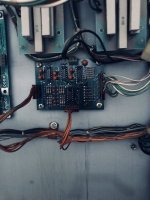
This pinbot has a couple of extra boards in the backbox - one is doing something with the specials solenoid switches. No documentation about this board in the pinbot manual, anyone got any info on this please?

Its connecting the playfield switch inputs for the special solenoid switches to both the switch matrix and also to the direct switch inputs on the main CPU board. Seems wierd. Was this something that came along from William at a later date?

IMG_7421.jpeg
 
I decided to go back to some bench testing, tested the switch matrix - seems to be running ok, but hard to tell - really need to be able to get into switch test mode, but anyhow PIA U38 is right in the battery damage area, so I re-soldered all it's pins. If this doesn't work then I will replace the chip..

Really frustrating that I cannot get into the test menus, so I had a closer look at the switch circuitry on the board. Some of this runs through the battery damage area, so could be a dodgy logic chip in here. But as a first go I' reflowed the solder to the pins that are a bit grotty.

Plugged it in and now we are getting somewhere - System boots, albeit in German language, got lights, and some sounds.
Best of all - the 2 coin door switches now work!!!! Yippee I can get into the test menus.

Managed to switch back to English language and run some switch tests, seems ok - ball trough optos working ok.

Set it on free play.

Started a game. It is working in a fashion, but when a ball drains, it just kicks out the other one, and doesn't advance the ball in play, so it's not ending a ball correctly. If I slowly move it through the trough so it gets more time on the first opto - the 'outhole' one then it does end the current ball, so something odd here. Optos receivers are wired up in the right order - from left to right then are "outhole" "Trough 2" "trough 1" - checked that's the right order in the manual. Although the manual seems to indicate real switches not optos - another change on this particular version of Pinbot

Anyhow, it feels like I'm on the home run with this.

To do:
1. figure out why ball drain not activating properly.
2, Sound has a lot of background noise and hiss - I guess needs re-capping
3. Lower display is not working - replace
4. translite needs affixing to a new front glass/acrylic panel and add lift trim and side trim etc
 
I have figured out why the ball drain isnt working, it is, but the problem is masked by a tougher issue - when I start a game, after a few seconds the game starts to clock up 'energy points' as I understand this should only be accumulated via the 3 pop bumpers. There is a big red light on the pf near the pop bumpers and this flashes each time. None of the pop bumpers are triggering. So it looks like a data problem to the CPU board via the switch matrix - It s a bit confusing - the pop bumpers are 'special solenoids' and are effectively directly triggered by their corresponding switches, but there is also a feed into the switch matrix as well. So it looks like its the switch matrix that is triggering off.

I run the switch tests and in test mode everything is all ok - no rogue switches triggering, I tried to simulate a game in progress to see if its a combo. The switch matrix is fed from the extra board I pictured above for the special solenoid switches. So I tried unplugging that at and the problem still there. The problem only stops if I unplug the connector for the switch matrix on the main cpu board. So does this suggest a wiring problem in the switch matrix, or is it an issue with the CPU board?

The switch matrix circuit is fed unto PIA U38 - via U 30&39 and U40. I have changed U39/U30 as socketed and no difference. Starting to suspect U30 PIA - gain it's in the battery damage area. I have re-soldered its pins, but perhaps now I should change it out and therefore rule it out of the equation.

Back to why the ball drain isn't working - the CPU is so busy with the false switch matrix triggering that it doesn't often see the 'outhole' switch get triggered, so misses it. I think once I solve the above problem, the ball drain will work fine. If I hold the ball drain opto for a few seconds, this generally works and does eventually trigger 'end off ball'
 
Replaced PIA U38 - Game working a lot better, but still got the phantom clocking of "Energy Points" - doesn't happen consistently - but it does happen every game, it then stops and then can restart at any time. Cant figure it out.

Replaced the MC14011 U30 & U39 chips - as these feed the sw matrix.

I have tested the whole switch matrix - on switch test - all ok

Physically tested all switch diodes - all ok

Tried disconnecting various switches (ones that can be unplugged from the matrix) - no difference

Tested the pull up resistors on the CPU board that hold the switch rows and cols high, all right Ohms

The "Energy Points" are incremented whenever a pop bumper is triggered, none of them are actually firing, as per explanation above.

If I disconnect the Columns - J8 of the switch matrix, the problem continues, This is really odd, because with the columns disconnected, there should be nothing to strobe each column to ground, yet this false switch triggering continues to happen.

If I disconnect the Rows - J10 of the switch matrix, the problem stops - suggests a switch wiring problem.

I guess next I should probe the Rows circuitry and logic with J8 Cols disconnected - nothing should be triggering, so see if I can find out which row it is. Pop bumpers on rows 4,5,8
 
flipping heck. found the issue.

one of the switch matrix rows is shorted to one of the lamp matrix rows. ffs. how does that ever happen.

i had a good search through the pf and can prove the short but there is no obvious sign of a connection anywhere. i’ve unplugged all the pf wiring from the back box and the short is still on the pf.

Looks like i am going to have to split open the wiring loom and chase down both of the connected wires, until I find the short. I could start chopping the wires to narrow down the search. but i’d rather not.

i’ve also looked for signs of damage and solder burns. can’t see any.

At least now i know wtf is going on.


Sent from my iPhone using Tapatalk
 
Alan, do the pop bumpers have a double stack switch. One to fire the coil and one to score the point?

There can be a lot going on under there and maybe a good place to start
 
no just a single switch. that goes into a circuit board. that splits it to the cpu in two ways. 1-to the special solenoid switch circuit and 2) to the switch matrix.


Sent from my iPhone using Tapatalk
 
BINGO !!!!

Found the short - burried deep in the playfield wiring loom. I could not see the actual shorrt but I separated the wires apart and the short has gone. Took several hours and I had to cut the switch matrix White/yellow row wire in two places to help narrow down whereabouts the short was.

There was no visible signs of that part of the wiring loom being damaged or messed around with. Very odd.

Anyhow - game now works as it should.

The aux power driver board has a relay on it to switch on the pf solenoids - this wasn't always coming on - looks like a header pin/connector issue, so reflowed that and it seems to work consistently now.
 
Tried to get the ball in play / credit / match display working - no joy it's knackered. Need to find a spare from someone.........
 
Last edited:
making amazing progress with that find Alan! Merry Christmas! o_O
 
sorry-a bit of a delay in progress updates on this. xmas then two weeks since 2 jan with c-19. ive only just got back on my feet.

Today i received a replacement match / credit display unit. Thus was tested working by the person i bought it off. but unfortunately not working in this machine. the credit units display is flickering badly. i changed the ribbon cable. no difference.

Looking at the circuit diagram, i can see U2 drives the credit part of the display. u2 is sane as u1 and both are socketed. i swapped the chips around and bingo! the problem has moved to the match units display. so looks like the driver chip is malfunctioning. I have ordered spares!

The sound is still not 100%. A quick look at the sound card and I can see a couple of bulging capacitors. Probably worth starting with those. also there is the dreaded hum as well. apparently these pinbots are renowned for it.
 
Had a great day with this project, I got up a silly o’clock this morning and decided to sort out the sound issues.

I really didn’t know where to start as there is sound circuitry on the main mpu board as well as the dedicated sound board itself

I took a gamble that the big caps on the dedicated sound card were a possible cause. they looked relatively new but had a bit of a bulge. I replaced them and all sounds now working ok Yey!!! result.

While testing I noticed a couple of switch errors. the left sling switches not working and on power on i get an error report about the left in lane switch. so that’s tomorrow’s job
 
Noticed the left slingshot wasnt firing, turned out to be a switch issue. Not easy to figure out as the switches for the slings are wired into a special 'splitter' circuit board in the back box, this seems to split the switch signal into two - one goes into the normal switch matrix and the other goes into the special switches input on the mpu board. At first I thought this board was the issue, but eventually turned out to be a poor connection in the connector block that takes the wires from the pf into the back box.

This project is almost complete. A few flasher lamps and other loose/dud lamps to sort, plus the new chip part on order to sort the match/credit display.

i was going to sell this, but it's such a nice fun game to play, so gonna keep it - but needs to go out on loan as outta space!
 
Last edited:
Today I got the replacement IC for the Display Driver board, popped it in nd now have a fully working Credit / Ball in Play / Match display. Yey! Thi pin is now going out on loan to a mate of mine who has just built a really nice garden room manshed (with heating).
 
Vee’s husband says:

Now I have this pin, this was a truly heroic effort and makes the problems I’m dealing with feel positively trivial!
 
Back
Top Bottom