What's new
Pinball info

Register a free account today to become a member! Once signed in, you'll be able to participate on this site by adding your own topics and posts, as well as connect with other members through your own private inbox!

Complete Pinbot mini shop log

AlanJ

Site Supporter
Joined
Dec 27, 2017
Messages
7,771
Location
Leeds, West Yorkshire
Alias
Alan
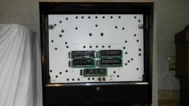
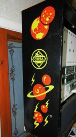
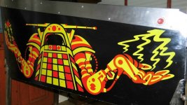
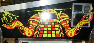
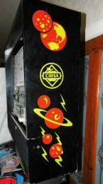
So my other unseen ebay purchase (in addition to the Bally Gold ball), was this Cirsa Pinbot. I am not really a fan of pinbot, but I want to get some experience on fixing SS Williams machines, so this is my first one.

Seller reported that machine more or less working, but CPU failing to boot. I figured this would be a good learning exercise.

Pics:

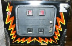
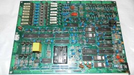
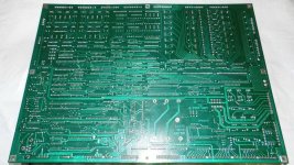
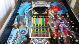
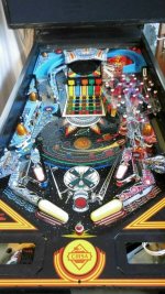
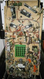
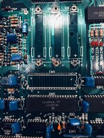
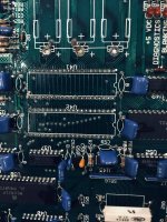
bb side.jpgbb.jpgcab side 2.jpgcab side 22.jpgcab.jpgcoin door.jpgcpu.jpgcpu2.jpgpf top.jpgpf.jpgtl.jpgunder pf.jpg

Sellers pics above.

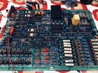
Looks pretty tidy and after an initial check of the wiring - everything looked ok and based on sellers detailed description of the current fault. I switched it on. Majority of pf lights and backbox lights GI come on - cpu doesn't boot - as expected.

Further investigation (I had to do some research on Williams Sys 11A cpu boards) - there are 3 leds. First one is to signify that +5v is present. Unfortunately it isnt lighting up.

Decided to start from scratch and go back to basics - so starting with the Power supply board.

It is not putting out any +5v at all. the +12v and -12v liens are ok. So I checked all the fuses - all ok

Next I checked the AC going into the Bridge recitifer - OK
the the output coming out of the Bridge - Good solid DC supply.

So something up with the rest of the 5V circuit.

I guess the big power transistor or the voltage regulator chip are the most likely suspects:
1607366869320.png

More testing / investigation tonight......
 
Last edited:
Looks great! Fancied this one too but wasn't confident of the electrical diagnosing.

I watched a Joe's Arcade on Pinbot the other night I think.

The Spanish version seem ok?
 
It’s cool. Just has the round inserts instead of square on the chest matrix. This game is fast becoming my fave of all time. I did a little video on mine although I never get round to finishing them so don’t know why I bother. For what it’s worth here it is
Love the video mate. Thanks for editing that. Its great getting the machine home and working through all the weirdness you find. Best bit! 😃
 
It’s cool. Just has the round inserts instead of square on the chest matrix. This game is fast becoming my fave of all time. I did a little video on mine although I never get round to finishing them so don’t know why I bother. For what it’s worth here it is
Love the ceiling rose connector and the ike led driver, or whatever it is.
 
Last night I tested the PSU board further:

1607411569411.png
Not getting anywhere near 5v on pins 2,3,4 of the IC, and pin 10 which should be 6.47v is a lot lower than that 2v. Think I'll get a new regulator chip and see if that sorts it.

Ordering parts is a pain at the moment - even if they are dispatched same day, they are taking over a week to arrive. grrrrrr
 
Nice, was looking at this one. Glad someone here got it. Had a Jackbot and always fancied this version.
Playfield looks lovely. Good luck with it.
 
The machine came with a translite, but no glass or lift trim etc. Looks like pinbot should have a metal not plastic glass lift trim - and apparently wider than other sys 11's, so that's going to be fun to track one down. Ordered 3mm acrylic sheet to mount it on. Acrylic is not cheap these days!
 
I noticed Pin-Bot in your other threads, but couldn't see that it's a Spanish version. I remember a local arcade had one briefly. One difference I recall is the Vortex skill shot moulding; that one didn't have anti-return wires, so a ball could run back out of it altogether, into the bumper area. Seeing under the playfield again, I see Bally-type 'linear' flippers and slingshots, and jet bumpers of a totally different design. Those two small boards at the front edge - are they some type of solid-state flipper drive, as I suspected at the time?
 
I noticed Pin-Bot in your other threads, but couldn't see that it's a Spanish version. I remember a local arcade had one briefly. One difference I recall is the Vortex skill shot moulding; that one didn't have anti-return wires, so a ball could run back out of it altogether, into the bumper area. Seeing under the playfield again, I see Bally-type 'linear' flippers and slingshots, and jet bumpers of a totally different design. Those two small boards at the front edge - are they some type of solid-state flipper drive, as I suspected at the time?

Yes i think they are flipper drivers. i’ve got stuff all over the pf glass at the mo with the back box insert down so not easy to get under the pf at the moment for some pics but i will do a comment on them later.

rant time- williams. i hate the drop down back box insert idea. much better a side opener !!!!! so hard to work with !


Sent from my iPhone using Tapatalk
 
I think that arrangement with the insert panel is a Spanish thing, the Pin-bots owned by work had the regular side-hinged panel. Are the displays safe when that's lowered?

Mind you, the Williams/Bally/1st time Stern insert favours the left-handed. Gottlieb had the insert open from the left, handier for most people
 
Last edited:
^ Aha, makes sense. I have to rest the insert on a cardboard box to support it, othrwise it's going to break something.
 
Following, one day I want to restore a pin bot as well. Watched one being restored on Joes Classic Arcade on YouTube and pin bot is one of my earliest memories of pinball so really need to get one someday :)
 
Well had some fun and games tonight. The PSU board in the machine is failing to deliver +5v. Ive got parts on order, but I then noticed a Williams PSU board on eBay, so bought that (thanks @mufcmufc) Same board, same Model number. The one in the machine is manufactured by "Unidesa", not williams. The replacement is a williams board. Both look identical. Plugged the new board in and......BOOM!!!!! - a capacitor and a varistor in flames. Bit of a shock, been a long time since I've had actual flames from a board!!!!

To cut a long story short - this Cirsa Pinbot seems to have a 50+VDC line for the solenoids whereas the Williams original has a 34VDC line for the solenoids. Still trying to get my head around this.

I checked the spec of the varistors - the Williams board rated at 38v, the Unidesa board rated at 60v. Same for the capacitors I guess, the Unidesa has 250v rating, the Williams one was clearly not up to the higher voltage.

Weird or what.

Checked the physical circuit all the way back to the transformer, and sure enough a 50v ac tap instead of the 26v tap specified in the williams manual.
 
Ooh dear, Alan,

What 50v solenoid power there is on the Williams-built early system 11 games (maybe only for flippers) derives from a bridge rectifier on a small '50v power' board, which I suspect may not be in the Spanish version.

Solenoid power apart (literally) for the bought-in board, is the 5v section working, and if so can the cpu start up? Provided that traces haven't been damaged, would it be wasted effort to transfer the 50v components?
 
Last edited:
yes a bit of a surprise. been trying to find a schematic for this particular pinbot but no luck. anyhow i think i’ve figured it out now anyway.

I’ve swapped out the power regulator from one of the psu boards to the other so now at last i have a fully working power supply board.

the cpu board now shows a lit +5v led. the diagnostics led just flashes. nothing from the blanking led.

So back to the issues the person i bought it from mentioned: battery leakage damage.
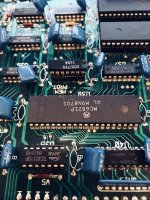
So i’ve taken out the worst affected 6821 chip right below the battery placement

17a4b2a0356e3ad3b1b7f0490411513e.jpg

Given all affected areas a vinegar/water wash and scrub. it’s now just drying off. i’ll clean up all those pads and holes - I guess a very fine sanding?

the other 6821 chip below the removed one also got a good dose of battery juice, so i think i’ll take that off as well.


Sent from my iPhone using Tapatalk
 
Cleaned up the holes today - how shiny and will take some solder - gave the board a good wash in IPA. Left to dry. Next I'm going to test all the hole traces to ensure they still go where they should and dont go where they shouldn't and also I'll test all the traces that run under those two chips as well. May as well be sure it's all looking ok before soldering something over the top.
 
I wondered if you'd make up a good power supply, swapping either the 5v reg. or the 50v stuff.

It's not occurred to me before seeing your picture above that the screening on the cpu board is contrary; everything visible about it except for the diagnostic l.e.d.'s is placed to suit the board being the other way up, when looking at it from the right side as you would in the Williams set-up (the wooden insert would be in the way from the left). I suppose that when the screening was altered between 11 and 11A, the draughtmen decided to put the screening for that portion, which was the obvious change AIR, the 'right' way up.

Also, the diagnostic l.e.d. flashes - rapidly as when running normally, or slower, more like the old Bally boards? There may be a label somewhere in the backbox, listing what the number of flashes mean. Though I wouldn't be surprised if it was for either or both of those PIA's.
 
Ive replaced the PIA's and no progress at all. same fault. The 5v led comes on solid, then the diagnostics led just continually flashes very fast. Nothing at all from the 3rd led - the 'blanking led' If I press the cpu switch on the board, then the game appears to 'reset' - i.e. the diagnostics lamp goes out for a few moments and they it returns to the rapid constant blinking.

So im thinking this means that the reset circuit is working? But my next step is to get the logic prrobe out and check that that reset circuit is actually sendding aa reset signal to the cpu chip.
 
There may be something amiss with the Blanking circuit - even if its l.e.d. shouldn't light as the Cpu boots up (which it does with Wpc boards), it should while the reset occurs, i.e. while the displays and feature lamps are shut off. If you've seen system 7 or 11 boards, with a 7-segment display chip for diagnostic, they changed the display from the normal '0' to an '8' during a reset; the centre segment was the 'blanking' indicator.
 
Last edited:
I can't even see where the 3 LED's are on the schematic??????? Anyone find them - its a new game or 'where's wally' - 'where's the LEDs'
 
I figured out that the schematics in the pinbot manual are incorrect - they show the 7 segment display circuit instead of the led circuit. So I looked up a 'close relative' of pinbot - F14 Tomcat, and downloaded its manual from ipdb.com. sure enough - it shows the 3 leds.

I traced the circuit back for the 'blanking led' and tried to figure out what is does. It looks like it's a protection circuit that shous down various things. Anyhow, it's controlled by U43 - a NE555 timer, which is triggered by Q50 transistor, which in turn is triggered by an invertor logic chip U36, which is connected to a pinout of one of the 6821 PIA's U51 - pin 4 - PA2.

Phew. So I started with the PIA - and probed the logic through, the pia pin is HIGH all the time, meaning the blanking led will never light. So, suspect the PIA - its next to the two I replaced! Damn.

I don't really want to replace another, but maybe it's inevitable!

I feel I'm looking in the right place now. Wasted time looking at an incorrect circuit diagram in the official manual ffs! I'm not feeling any Williams love - I'm obviously a Bally man !!
 
Got the board out and properly set up on the bench with a test rig again (same one I made for looking at Bally MPU boards) - except dont need to 20v circuit just to +5v and +12v for this Williams board

IMG_7410.jpeg

Did some more logic probing on the Blanking circuit. Pin 4 of U51 (PIA) chip is the start of the signal, this connects to U51 (4 to 16 decoder chip) and U36 - the hex invertor that goes on to the transistor NE555 and then to the blanking led.

As I was fiddling about I managed to get the blanking led to come on - but it is intermittent, then after a while it went back to just staying off. So I suspected a loose connecting - soldered up a loadd of pins no luck. I then did a short test and found that Pin 4 of the PIA U51 is shorted to the +5v rail !!!!! No wonder it was high all the time. I then tested this PIA and sure enough Pin 4 showing dodgy on a diode test. So could be the PIA, but of course it is wired to the other 2 chips, either of which could be faulty.

So, I decided to snip pin 4 of the PIA so I could test it without removing the whole 40 pin PIA chip. Once I did this Pin 4 tested as fully working on a diode test! So, phew it's not the PIA

Now to look at the 2 other chips. U51 and U36................
 
I snipped of the leg of the U36 chip - this being the one I favoured most to be faulty, and sure enough it is. Pin 13 is shorted to the Pin14 VCC on this chip, so looks like it h blown - it is also in the acid damage area so thats why I suspected it over the U51 chip (which is not in the acid damage area).

Took the chip out, cleaned up underneath and the pins, tested for continuity and no shorts, all looked good, so soldered in a socket. I managed to find a 7404 chip in my stock of chips - its a really old thing with black oxidied legs, but it will do until I can get a new one,

Popped it in and hey presto - We now have a working blanking circuit. The board booted up first time and with no errors! Yippee!

You can see the rather manky looking 7404 chip below. But it works! I probe tested all the inputs and outputs and all look ok, on the bench.

IMG_7411.jpeg


I'll run a few more logic tests and then try it in the machine.
 
Reading that the schematic given was for 11 rather than 11A reminds me that at least one of works' Pin-Bots did have an original 11 cpu board, fitted out with the l.e.d's instead of the display chip. It was a proper higgledy-piggledy arrangement of the diodes and their resistors, requiring a label with arrows pointing out which diode was which.

And they had 12v and ground wiring laid into the playfield wiring to the target bank, even though opto drop targets ended up being deferred until Millionaire
 
Back
Top Bottom