What's new
Pinball info

Register a free account today to become a member! Once signed in, you'll be able to participate on this site by adding your own topics and posts, as well as connect with other members through your own private inbox!

Mr & Mrs Pacman. Blowing fuse F3 on the Power Module.

DanLewell

Registered
Joined
Jul 21, 2011
Messages
1,041
Location
Northampton, UK
Trying to work through this issue.

I want to get it fixed before pinfest as its supposed to be going there, (and @Poibug will be ****ed at me if I take it broken and and ask him to have a look when I get there!! ;) )

So let's see if we can work out what's going on with it.

I'll go through in baby steps because I'm trying to improve my diagnostic skills so I can actually work out what's happening when something goes wrong, so I'll go through what I've done, if I've missed any steps or forgotten something obvious, please let me know so I can try to get better at working out what's wrong.

So, first thing is what happens. Games boots and starts flashing into attract mode but about 2 seconds later (possibly before it's finished booting to be honest ) the fuse blows.

So, after a couple of fuses I pop the circuit breaker in.
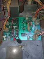

20210803_210805.jpg

There isn't actually much happening on this board but looking at the schematic fuse f3 is only in the circuit with the bridge before it goes to 1 of the pins on J3 (the 12pin connector.)
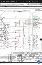
Screenshot_20210803-221523_Gallery.jpg

So, disconnect J3 and reboot to see if it's a problem on the board or further upstream. Turn it on and the fuse doesnt pop. Reconnect it and the fuse pops again.

So now I need to see where pin 10 is going.

Different page in the schematic shows where it's going.
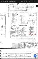
Screenshot_20210803-221609_Gallery.jpg

So this tells me the colour of the wire (70. 7 = Orange 0= no trace) and where it goes to: A3J3-12 and A8J1-10 (I think. I'm not sure about it going to two places to be honest. )

A8 is listed in the schematic as the talk and squawk board, I struggled to find A3 in the schematic, but eventually found it as part of the solenoid driver voltage regulator schematic.
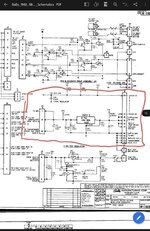
Screenshot_20210803-221645_Gallery.jpg

But this is where I'm getting to the limit of what to test and why I should test that thing.

I pulled the connector from this board (but left the talk and squawk board connected) and fuse didn't blow, so it looks like it is this board, but it also looks like the voltage comes in (on pin 12) and goes straight out on the same connector on pin 11) , so is it this board or the mpu to look at next?

What is the next step in working out what's wrong?
 
Thanks Gary, my thinking was that it wouldn't be the bridge rectifier because it doesnt happen when I disconnect the connector, but it won't take long to swap them so no harm in trying.

I'll report back in later tonight.
 
unplug the connector to the mpu board, and then you’ve isolated it just to the sdb board. it’s most likely a problem on the sdb board, but it could be mpu board, so by unplugging mpu you can determine which.

On the sdb board there are 3 capacitors c23, 24,29 i think- if any of those is faulty could be shorting the 11.9 to ground. the big one is one to replace if it hasn’t been replaced already? 40 years old is probably well past it’s working lifetime
 
unplug the connector to the mpu board, and then you’ve isolated it just to the sdb board. it’s most likely a problem on the sdb board, but it could be mpu board, so by unplugging mpu you can determine which
Did this quickly this morning, with the mpu disconnected it still blows the fuse,

So looking like the sdb.

I'll have a proper look at it tonight, but does the fact that it takes a second or two to blow point to a capacitor issue, as its starting to charge then falling over? (Or am I talking out of arśe again?!)

The big cap has been replaced previously, doesn't mean its definitely OK, but I'll test it tonight and see what I get from that and the other caps. 20210804_085544.jpg

Other than the caps and a couple of resistors there is only the 5v regulator in that bit of the circuit. Is that the silver component with the massive heat sink?

Is there any way to test that?
 
Other than the caps and a couple of resistors there is only the 5v regulator in that bit of the circuit. Is that the silver component with the massive heat sink?

Is there any way to test that?

Yes, it is and yes there is a way to test it. You've already highlighted it...


That's to measure the voltages at TP1 and TP5.

Have you another game that you can swap the board with to help rule out other boards/issues.
 
Cheers Peter.

Yeah, I've got a couple of other machines in the warehouse with the same boards, but they're projects so can't assume the boards are ok.

It takes a second or two before the fuse blows so I should have time to get the readings from the test points.

Red probe on the Test point, Black probe on the ground Braid or somewhere else?
Yep.

I'd also grab one of the other boards (if they're easy to get at) as it might be a quick win.
 
  • Like
Reactions: DRD
Just another quick though? Are you putting in the right type of fuse? Slow blow.

When power is first applied the large 15,000 uf capacitor is basically a short circuit for a few moments until it charges up, so you get the maximum current draw within the first second or so after power on.

Also, the original capacitor was 11,700uf but has been replaced with a larger 15,000uf, which is actually ok and a lot of folk recommend this size, but, a larger capacitor does draw more power initially, so you may in theory need a slightly bigger fuse to handle that extra power surge. Having said that i’ve upgraded many of mine to 15,000uf and not needed to update the fuses.
 
Do you have history of this board working? There are fakes about of Q20.

I think the fault is in the 5V reg area, but for completeness have you measured the 11.9 VDc leaving the power board at TP3 (J3 disconnected).
 
What happens if you disconnect everything except power in to the power bd?
Fuse is OK with J3 disconnected.

Is it possible that the fuse only blows when a load is applied? Or would it blow anyway if the fault was on the power board?

I'd also grab one of the other boards (if they're easy to get at) as it might be a quick win.
Took a couple of spare boards home with me tonight. One of them showed an error on the big cap when I put my multimeter on it. The other one tested OK, so I thought I would try that in the machine. Same fault, the fuse blows after a few seconds.

Just another quick though? Are you putting in the right type of fuse? Slow blow.
Yep, slow blow. Although at the minute it's got a circuit breaker so I don't run out of fuses troubleshooting. It's wierd as it doesn't blow immediately, it blows after a few seconds.


Do you have history of this board working? There are fakes about of Q20.

I think the fault is in the 5V reg area, but for completeness have you measured the 11.9 VDc leaving the power board at TP3 (J3 disconnected).
Yeah, the machine was working OK. Uts been used for league meets and handled being on all day, but then it popped and hasn't come back.
 
So tonight I tried the board from another machine as suggested by Peter. But as I was getting the same error, it make me suspect the power board again.


So with J3 disconnected I thought I would look at the test points on the power board. They are all roughly where they should be, BUT, the values are jumping up and down rather than being stable, so can't really take a reading to tell you what they are.

I lent my decent multimeter to one of the lads at work who promptly lost it. :mad:
So I'm trying to troubleshoot with a cheap crappy one. Think I need to treat myself to an early birthday present so I can carry on troubleshooting.

I couldn't get a reading on the big cap of the original board at all, so haven't ruled that out as faulty, but don't trust my meter so not sure about that.

I'll check back in once I've got a meter I can rely on.
 
could be the bridge rectifier on the power board, they can do odd things when they fail. ie test out ok until you put some load through them.

you should be ok even with a cheap meter.
 
Yeah, looking at the schematic again, it's not actual a bridge rectifier, it uses 4 separate diodes to do the same thing instead, so could be one of those. The 2 bridge rectifiers are for different voltages.

I think Flash gordon has the same power board, so might borrow that tomorrow to see if it works with a different power board in.

The readings on the meter won't settle at all, and it's one of the auto sensing ones that try to work out what range it needs to be at etc. I've ordered one from amazon that is similar to the one that I used to have so will see what it says when that get here.
 
Change the regulator, the bridges, the diodes and the electrolytic capacitors.

That machine is 40 years old.

If you plan to take it to pinfest where it will be on for two days solid then I would do this (I generally would do this on any from this era even if it worked). The game will get hammered, if you do not do this kind of work before - more than likely it wont last.

The resistors look like they have had a hard life on the power board too. I would change them for new ones as well.
 
Yep, slow blow. Although at the minute it's got a circuit breaker so I don't run out of fuses troubleshooting. It's wierd as it doesn't blow immediately, it blows after a few seconds.

That's the advantages of circuit breakers, they give you an extra bit of time before they trip.

They are all roughly where they should be, BUT, the values are jumping up and down rather than being stable, so can't really take a reading to tell you what they are.

I half expected this, I suspect the new board has cap issues so there is no stable reading.

Swapping the FG board would confirm the problem area.

I concur with what pick holder has just said.
 
I half expected this, I suspect the new board has cap issues so there is no stable reading.
Readings are all over the place on the power board with j3 disconnected.

Will see if the flash gordon board works, but agree its probably a good idea to sort the potentially dodgy components out either way.
 
I'd agree with @Pick Holder replacing some of the main parts, due to age.
Especially caps- I replaced every cap on my Centaur sound board, plus others on power board etc etc. Just buy good quality caps- some crappy new ones aren't right even when new.
I remember chatting to other collectors about this issue.
 
Lou and the kids are away this week so I've got every evening free to tinker.

New meter arrived at the weekend, so I'll have a look at all the test points and report back.
 
I'd agree with @Pick Holder replacing some of the main parts, due to age.
Especially caps- I replaced every cap on my Centaur sound board, plus others on power board etc etc. Just buy good quality caps- some crappy new ones aren't right even when new.
I remember chatting to other collectors about this issue.

Thirded - Electrolitic Caps have a best working life of 20-25 years....
 
Ok, back to basics now I've got a meter that I can trust.

I've disconnected all output connectors from the power board and tested all of the test points.

We're getting:
TP1 7.15 (Should be 6.5)

TP2 180.6 (should be 230)

TP3 33.22 (should be 11.5 I think. The schematic is a bit blurry - deffo 11.something though, not 33.something)

TP4 Nothing first of all. Check schematic again, this is AC not DC. Doh! Getting 7.0 (should be 6.5)

TP5 44.62 (should be 43)

So, voltages on tp1, 4 & 5 are there ot thereabouts.

TP3 is way too high, almost certainly why I'm having problems. I guess it will have knackered the 5v rectifier and other components in that circuit on the solenoid board from being way too high?

TP2 is low, is that going to be causing problems as well?? Following through the same method from above we can see that feeds j3pin6 on the sdb. Which is the 190v regulator circuit (shown just below the one I highlighted above) range according to the schematic is 230v + or - 27v. So lower than it should be, but all the 190v is used for are the displays and they are working OK ( or were when it last booted without blowing the fuse. )
So for now at least, "if it ain't broke don't fix it" for that one.
 
Looking at the circuit for TP3 all we've got is 4 diodes (doing the job of a bridge rectifier)

Manual shows them as 3A Diode. No other info. Are there other characteristics for a diode or are all 3A diodes going to be the same?

EDIT: looking online it is suggested I replace these with 6A50 diodes or 6A4 (Which are 6A 400v)

Going to check the input voltages to this board from the transformer too.
 
Last edited:
Input voltages
TP3 circuit is 14.84 (should be 14.2)

TP2 is 186.3 (should be 170)

These look OK (ish) so think the transformer itself is OK (which is to be expected, I don't think they go wrong very often)
 
to2. the 180v circuit is probably ok

to3 - check to see if you are getting any AC voltage (it should be small) if it’s large replace the diodes.

power supplies often. report larger voltages when not under a proper load.
 
I'm sure you're on the right track re. the diodes a good plan to replace them. Do you have a diode function on your new DMM? Would be interesting to clip them and compare results as you have 4x identical.
 
Back
Top Bottom