What's new
Pinball info

Register a free account today to become a member! Once signed in, you'll be able to participate on this site by adding your own topics and posts, as well as connect with other members through your own private inbox!

Mr & Mrs Pacman. Blowing fuse F3 on the Power Module.

Went up to see Andy (@pinballmania ) and pick up some parts. Talked the problem through with him and he seemed to think it unlikely that it was the diodes.

I got some anyway just in case, but as there is nothing else in that circuit once you've removed the connectors and the fuse, they are easy enough to test. They all tested OK. Put in a board from a different machine (not known to be good unfortunately, but just wanted to check the voltages) and got pretty much the same voltages on the test points.

So original board back in.

I tested the big cap on the solenoid board and it looked OK, but also got a constant beep one time when I tested it so replaced it anyway.

Only plugged in the connector to do with the 5v section, and got ready to check the voltages.

Test on the rectifier board came in at about 12v. So thought I'd cracked it.

Powered off so I could mess about getting playfield down and getting to the solenoid board. Powered up again and got ready to test the voltages on the test points of the solenoid board... fuse popped again. Grrrr.

So took the board out again and replaced the 5v regulator. Put it back together and it looks good. Test point voltages for the 5v section we're roughly 12v and 4.95v.
 
Plugged all the connectors back in the backbox and tried to start a game.

Grrrr, not working.

Stupidly forgot that I had only plugged 1 connector into the regulator board earlier. Doh!

Plugged the rest in and it lives!! Can start a game, ball pops out, flip about a bit, then it goes up to the top saucer, I to the pac maze, all good, BUT then it doesn't pop out of the saucer.

Gone through the solenoid test and some aren't firing, others are firing twice (once when they are supposed to and once when something else is supposed to)

I think it is to do with the solenoid expander board, but not looked at it properly yet.
 
I think it is to do with the solenoid expander board, but not looked at it properly yet.
If it is driven by that check the bulb near the board is present and working

Edit. I think it has to be an inandescent bulb too (or resistance altered for LED)
 
Last edited:
  • Like
Reactions: DRD
It's not the solenoid expander.

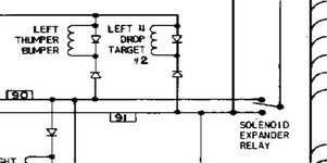
That is clicking away and the lamp is coming on and off. And looking at the schematic it isn't the coils on 4he same wire firing. (Unless I'm understanding it wrong - which is fairly likely)

So if it was an issue with the expansion board and it tried to fire the left pop bumper it would fire left 4 drop 2.
But what actually happens is instead of firing pop bumper it fires one of the slings.

Screenshot_20210813-221744_Acrobat for Samsung.jpg

It had this exact same issue before a league meet a few years ago, and we couldn't work it out. ( I say we, I mean @Telboy ) but then it started worked for no reason and has been good ever since.

Also, it's affecting solenoids that don't go through the expander board so that'd definitely a red herring.
 
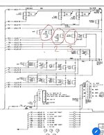
So narrowing it down to solenoids that don't go through the expander (so we can definitely rule that out.) I'm looking at the saucer kickouts.

Screenshot_20210813-222514_Gallery.jpg

These should fire as 1, 2 and 3 in the solenoid test. But what actually happens is right saucer fires for 1, nothing fires for 2, and right fires again for 3.

So, I'm ignoring 2 for now.

And following the schematic I'm looking at A3J2-4 and A3J2-10

Is there something on A3 that could be firing A3J2-10 whe it should be firing A3J2-4??
 
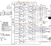
So, looking at the schematic for the solenoid driver board again.

Screenshot_20210813-225733_Gallery.jpg
It's firing pin 10 of j2 instead of pin 4.

The only shared component is U2.

Another misfire that's happening is left sling instead of left pop bumper.
Firing pin 9 of J5 instead of pin 12.

Again only shared component is u2.

Is it likely that u2 has gone funny? Would that be likely to cause the wrong outputs to fire? Or is it more likely to be further upstream with whatever is driving driving this chip?

Any way to test that? I've got a logic probe if that helps but I'm a newb so you might have to tell me where to shove it!!
 
It is probably the control wires between the mpu and driver board reseat j4 and on mpu, j4 again

i’ve had similar issues on another bally with same board set
 
Hi Dan
Sound like your solenoid select lines are confused check the plugs on
MPU j4 pins 1234&pin10
Solenoid board j4 pins 345&6
Squawk & stalk j1 pins 1234&12
For dry joints bent pins loose wire etc
These are the address lines
Could be you disturbed them while testing
Hope is helps
Telboy


Sent from my iPad using Tapatalk
 
I have had a similar fault in the past,I re pinned my connectors and it solved the issue,sometimes the pins are broken inside the old housings and you don't even notice from the outside
 
Cheers guys. I'll have a look at the header pins on the solenoid board. The mpu is an altek so less likely to be the pins at that end.

Plus the solenoid board has been in and out like a yo-yo, so I'm more likely to have done something to that.

I'll let you know how I get on.
 
Grab a magnifier and check those connector pins. Also check the bottom of the cabinet for broken bits as they tend to gather there when the connectors are pulled off.
 
I repaired a sea witch recently - and that had bad pins and connectors. Replaced them and faults disappeared. It will take you some time but it is worth doing. They get corroded and start doing funny stuff.
agree 100%. don't waste time inspecting the connectors just replace.(the times we have "inspected and come to the conclusion they are all ok" they never are!) particularly if you are taking the game to a show, or else other faults will develop and you will just be taking the backglass off every 6 games.......
its the only way to get a reliable game long term. best to crimp and solder the connectors for 100% confidence.
FOR WHAT ITS WORTH..........
if it were me I would be replacing connectors at j3 j4 solenoid pcb. (j4 is the solenoid BCD's and enable, j3 GND, and voltages)
MPU pcb. j2 j4 connectors. (j2 playfield switches, j4 solenoid/snd, BCD, voltages).
tedious but essential maintenance which will reap rewards.
Keef.........
 
Sounds like I've got a job ahead of me tomorrow then.

New header pins on the solenoid driver board and new crimps all round.

Thanks for all the help guys.
 
Back
Top Bottom