Just noticed the date on the invoice from Replay Leisure Equipment is dated 23 October 2013, almost 3 years ago to the day! Wonder what it looked like back then? I also wonder what £245 of labour got you? Assuming that's five hours at £49/hr. Would that be about right?
Pinball info
You are using an out of date browser. It may not display this or other websites correctly.
You should upgrade or use an alternative browser.
You should upgrade or use an alternative browser.
In Progress Lost in the PAC MAZE... Another Obsessive Restoration
- Thread starter Nedreud
- Start date
-
- Tags
- bally mpmm project restoration
I've also just realised that this is the third classic Bally pin I've saved. PARAGON was the first, which was always a project, but GOLD BALL I bought for spares and realised was complete and savable. And now PAC-MAN... saved from the jaws of wanton destruction... saved from being parted out and burnt 
21-October-2016
FIXING THE SOLENOIDS
Very excited after yesterday but I wanna play the whole game! Having no solenoids working (except the flippers) is frustrating. Went to Maplin last night a picked up a 10-pack of 1 Amp Time Delay (Slow Blow) 31mm fuses - code GL91Y, £3.29. Popped one in under the playfield and turned the game on... Snap! went the left slinghshot and Bang! went the fuse. I guess we've got a dead Q transistor on the solenoid driver board.
I removed the A3 AS-2518-22 SOLENOID DRIVER/VOLTAGE REGULATOR MODULE from the backbox to test it on the workbench. Immediately Q9 is looking suspicious as it's a different transistor TIP102 from the others, all original 2N6045. On the underside Q9 has clearly been reworked and not particularly well. Blobby soldering and scraping in between the tracks. Also, Q18 and Q19 are missing. Q18 doesn't matter as it's "Not Used" but Q19 is the Coin Lockout. Again, not ultra critical but no reason why it needs to be missing. I also too the opportunity to cable tie capacitor C23 into place permanently.
Anyway, I tested all the Q transistors with the multi-meter on DIODE setting. Testing is very simple. Just put the black lead on the metal tab of the transistor to be tested and then touch the red lead onto each of the three legs in turn (this is more easily done on the underside and I use a crocodile clip to connect the black lead to the metal tab). The middle leg should read zero, and the outer legs should read between 0.300 and 0.600 volts. Then swap the leads over and clip the red cable to the transistor tab and use the black lead to probe the 3 legs. You should get the same results again. If any reading is different or out of the 0.300 to 0.600 range replace the transistor with a TIP102 (lucky I recently a job lot of 100!).
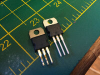
In my case all the Q transistors were fine apart from Q9 which read zero on all tests. Dead. And this will cause whichever coil it's set to drive to lock on constantly. Checking the schematic (see blow) Q9 is responsible for driving the LEFT SLINGSHOT (by default) or the LEFT 4 DROP TARGET #4. This "or" is controlled by the SOLENOID EXPANDER MODULE AS-2518-66 that's mounted on the underside of the playfield. The SOLENOID EXPANDER is controlled by a lamp circuit on the AS-1518-23 LAMP DRIVER MODULE and it's simply a relay that switches power between 2 sets of solenoids. Clever way of expanding the number of momentary solenoids that can by controlled by the MPU without changing the SOLENOID DRIVER board. It just required a single lamp channel to be able to control an extra 8 momentary solenoids. Notice that the extra solenoids under control are the individual reset coils on the drop-targets and not used in the heat of gameplay, so no conflict of interest that both solenoids need to be fired at the same instant. Basically this game is able to remember the state of the drop-targets between players. The main coil resets all the targets then the small coil on each target can be fired to drop them as required.
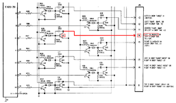
Whilst I had the board on the bench I also checked the blocking diodes CR1 to CR19 that feed each Q transistor as these often fail together. All tested fine. Just use the multi-meter on DIODE mode again and you should a reading of between 0.400 and 0.600 volts. Swap the leads round and you should get a value in the same range again. If you don't replace the diode with another 1N4004.
After putting the board back in the game I put the game into TEST MODE using the button on the ALLTEK MPU. First press is Lamp Test Mode which flashes all lamps. Surprised that that I only seem to have 1 dead lamp, the down arrow for the PAC MAZE. Second press is Display Test Mode which cycles all the displays to show 0 to 9 on every digit, e.g., 0000000, 1111111, 2222222, etc. Third press is Solenoid Test Mode and I'm pleased to hear all the solenoids fire in order (except the coin lockout). Fourth press is Sound Test Mode and the SQUAWK & TALK starts repeating a very annoying alarm! Fifth press and we're into Switch Test Mode. For this the displays will flash the number of any stuck switch with a ping sound or silently display "0". The displays shows "05" which is the TROUGH KICKER... the ball is in the drain hole! Take it out and with no further sound the displays show "0". Yes! No stuck switches. Next I check the backbox information and activate all the numbered switches in order. I've got a couple of dead switches:
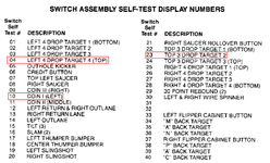
Number 10 isn't a problem as won't be using coins but a quick inspection reveals it's simply because one of the wires has come off. #04 and #23 are problematic for gameplay because it means the MPU doesn't know when either the LEFT or TOP drop-target banks have been completed, thus affecting the rules. Suspect loose wires, dirty contacts, naff IDC connectors or dead diodes but will deal with them later. The whole game is going to be stripped and rebuilt after all!
After a quick wipe over with Mill Wax (I don't think there's much more harm I can do to this playfield) it's time for a few games Damn, this thing plays fast and all three linear flippers are strong. Even the linear slingshots don't hang about (I replaced the linear slingshot on my GOLD BALL with the older vertical type as it seemed weak). Slight issue with holding the ball on the left flipper: there's a small chunk missing in the clear lower plastic so the ball hangs up even when the flipper is down (you can see this happening in the video below).
I was also very pleased to make the shooter skill shot FIRST TIME
FIXING THE SOLENOIDS
Very excited after yesterday but I wanna play the whole game! Having no solenoids working (except the flippers) is frustrating. Went to Maplin last night a picked up a 10-pack of 1 Amp Time Delay (Slow Blow) 31mm fuses - code GL91Y, £3.29. Popped one in under the playfield and turned the game on... Snap! went the left slinghshot and Bang! went the fuse. I guess we've got a dead Q transistor on the solenoid driver board.
I removed the A3 AS-2518-22 SOLENOID DRIVER/VOLTAGE REGULATOR MODULE from the backbox to test it on the workbench. Immediately Q9 is looking suspicious as it's a different transistor TIP102 from the others, all original 2N6045. On the underside Q9 has clearly been reworked and not particularly well. Blobby soldering and scraping in between the tracks. Also, Q18 and Q19 are missing. Q18 doesn't matter as it's "Not Used" but Q19 is the Coin Lockout. Again, not ultra critical but no reason why it needs to be missing. I also too the opportunity to cable tie capacitor C23 into place permanently.
Anyway, I tested all the Q transistors with the multi-meter on DIODE setting. Testing is very simple. Just put the black lead on the metal tab of the transistor to be tested and then touch the red lead onto each of the three legs in turn (this is more easily done on the underside and I use a crocodile clip to connect the black lead to the metal tab). The middle leg should read zero, and the outer legs should read between 0.300 and 0.600 volts. Then swap the leads over and clip the red cable to the transistor tab and use the black lead to probe the 3 legs. You should get the same results again. If any reading is different or out of the 0.300 to 0.600 range replace the transistor with a TIP102 (lucky I recently a job lot of 100!).

In my case all the Q transistors were fine apart from Q9 which read zero on all tests. Dead. And this will cause whichever coil it's set to drive to lock on constantly. Checking the schematic (see blow) Q9 is responsible for driving the LEFT SLINGSHOT (by default) or the LEFT 4 DROP TARGET #4. This "or" is controlled by the SOLENOID EXPANDER MODULE AS-2518-66 that's mounted on the underside of the playfield. The SOLENOID EXPANDER is controlled by a lamp circuit on the AS-1518-23 LAMP DRIVER MODULE and it's simply a relay that switches power between 2 sets of solenoids. Clever way of expanding the number of momentary solenoids that can by controlled by the MPU without changing the SOLENOID DRIVER board. It just required a single lamp channel to be able to control an extra 8 momentary solenoids. Notice that the extra solenoids under control are the individual reset coils on the drop-targets and not used in the heat of gameplay, so no conflict of interest that both solenoids need to be fired at the same instant. Basically this game is able to remember the state of the drop-targets between players. The main coil resets all the targets then the small coil on each target can be fired to drop them as required.

Whilst I had the board on the bench I also checked the blocking diodes CR1 to CR19 that feed each Q transistor as these often fail together. All tested fine. Just use the multi-meter on DIODE mode again and you should a reading of between 0.400 and 0.600 volts. Swap the leads round and you should get a value in the same range again. If you don't replace the diode with another 1N4004.
After putting the board back in the game I put the game into TEST MODE using the button on the ALLTEK MPU. First press is Lamp Test Mode which flashes all lamps. Surprised that that I only seem to have 1 dead lamp, the down arrow for the PAC MAZE. Second press is Display Test Mode which cycles all the displays to show 0 to 9 on every digit, e.g., 0000000, 1111111, 2222222, etc. Third press is Solenoid Test Mode and I'm pleased to hear all the solenoids fire in order (except the coin lockout). Fourth press is Sound Test Mode and the SQUAWK & TALK starts repeating a very annoying alarm! Fifth press and we're into Switch Test Mode. For this the displays will flash the number of any stuck switch with a ping sound or silently display "0". The displays shows "05" which is the TROUGH KICKER... the ball is in the drain hole! Take it out and with no further sound the displays show "0". Yes! No stuck switches. Next I check the backbox information and activate all the numbered switches in order. I've got a couple of dead switches:

Number 10 isn't a problem as won't be using coins but a quick inspection reveals it's simply because one of the wires has come off. #04 and #23 are problematic for gameplay because it means the MPU doesn't know when either the LEFT or TOP drop-target banks have been completed, thus affecting the rules. Suspect loose wires, dirty contacts, naff IDC connectors or dead diodes but will deal with them later. The whole game is going to be stripped and rebuilt after all!
After a quick wipe over with Mill Wax (I don't think there's much more harm I can do to this playfield) it's time for a few games
I was also very pleased to make the shooter skill shot FIRST TIME
Last edited:
Looking good Peter, keep it coming
Hi, Peter,
I've just remembered that an earlier M&M Pac-Man, #3282, is the only machine where I've seen a heat sink added to one of the solenoid drive transistors (for the outlane gate). That solenoid is energised to close the gate (the normal condition) at game start, and remains on until a player earns an opening or the game ends. It was the machines' original pcb, and looked factory done.
I've just remembered that an earlier M&M Pac-Man, #3282, is the only machine where I've seen a heat sink added to one of the solenoid drive transistors (for the outlane gate). That solenoid is energised to close the gate (the normal condition) at game start, and remains on until a player earns an opening or the game ends. It was the machines' original pcb, and looked factory done.
I love the detail on this thread. It makes me think I could fix completely dead machines myself.
I cant, but it makes me think I should give it a go.
Whats the worst that can happen...
I cant, but it makes me think I should give it a go.
Whats the worst that can happen...
For my understanding, shouldn't diodes test null/open when tested in their reverse direction?Just use the multi-meter on DIODE mode again and you should a reading of between 0.400 and 0.600 volts. Swap the leads round and you should get a value in the same range again. If you don't replace the diode with another 1N4004.
Me thinks Peter is getting transistors and diodes mixed up.For my understanding, shouldn't diodes test null/open when tested in their reverse direction?
Perhaps he's testing that we're reading all the detail

Ooh, thanks! Good tip. I think something is wrong my gate because I've just realised it's always closed. That is, it always saves a ball headed down the left out-lane. I'm guessing it should normally be open to allow the ball to drain unless, like you said, some bonus or special has been earned. This is my first game with a gate mech so will be interesting to learn something new. I'll have to try and find a photo of the heatsink and see if I can get something similar.Hi, Peter,
I've just remembered that an earlier M&M Pac-Man, #3282, is the only machine where I've seen a heat sink added to one of the solenoid drive transistors (for the outlane gate). That solenoid is energised to close the gate (the normal condition) at game start, and remains on until a player earns an opening or the game ends. It was the machines' original pcb, and looked factory done.
You can fix dead machines yourself! It just takes a methodical approach to testing. These old games are generally very simple. It's basic electronics really. It just looks hard because there are lots and lots and lots of simple circuits repeated over and over again leading to a spaghetti junction of wires!I love the detail on this thread. It makes me think I could fix completely dead machines myself.
I cant, but it makes me think I should give it a go.
Whats the worst that can happen...
What's the worst that can happen? Well you could kill yourself if you mess around with mains electricity and you're not careful. Other than that you'll end up with a machine that still doesn't work
Yes, but this is a cheaty test with the diode in-situ. To test conclusively you'd need to unsolder one end. If the diode is working you'll get 0.400 to 0.600 in one direction (forward bias) and OL the other (reverse bias). Any readings outside these value should result in replacing the diode. I wouldn't bother unsoldering a diode without reason to suspect it's faulty.For my understanding, shouldn't diodes test null/open when tested in their reverse direction?
I am sure most will agree that 6800 Ballys are the best for resurrection as they are well built and parts readily available. 80s Williams and gottlieb a lot more PITA . Zaccaria can be tricky to get going BUT the playfields are never worn so always turn out nice.
Ooh, thanks! Good tip. I think something is wrong my gate because I've just realised it's always closed. That is, it always saves a ball headed down the left out-lane. I'm guessing it should normally be open to allow the ball to drain unless, like you said, some bonus or special has been earned. This is my first game with a gate mech so will be interesting to learn something new. I'll have to try and find a photo of the heatsink and see if I can get something similar.
I saw one once where the mechanism was maladjusted, so that the gate would drain both l/h lanes unless a player had earned an opening, whereupon it moved to the 'normal' (closed*) position. On this game, I think opening the gate is a reward from the upper target bank.
* I'm referring to the gate wireform being vertical as normal/closed, i.e from the viewpoint of a ball in the l/h out-lane
Thanks @Jay Walker. Going to take a look this afternoon whils the Mrs is out 
So I'm not sure I understand how this mech works if it's a single continuous coil? I can see the coil operates a little crank to rotate a spindle that the gate is mounted on but does that mean that when the coil is OFF there should be a spring to pull it back to the OPEN (ball saving) position? That is, at game start the coil is turn ON and pulls against the spring to move the gate into the CLOSED position thus allowing drains until the player earns the reward to OPEN it at which mount the coil is switched OFF and the spring returns the gate to CLOSED.
I'm only guessing at this point!
That's the correct way it works the gate opens after the upper 3 bank is dropped twice, when the ball is saved from draining the gate closes
It's controlled by a small button type coil below the gate I don't recall seeing a one of the solenoid transistors having a heatsink will have to have a look you have intrigued me now.
It's controlled by a small button type coil below the gate I don't recall seeing a one of the solenoid transistors having a heatsink will have to have a look you have intrigued me now.
22-October-2016
LEFT OUT-LANE GATE
After a few games I noticed that the diverter gate in the left-hand out-lane was always closed, i.e., every ball that went down the out-lane and should have drained was being diverted into the in-lane and saved.
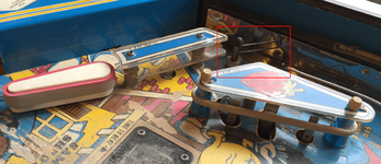
First I checked for any obvious mechanical defects by removing the mounting bracket for the coil to release the actuator arm from the gate shaft:
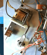
The rotation of the gate shaft isn't perfectly smooth but not enough to prevent the gate from moving and not enough to resist the return spring on the coil. This coil is driven by one of the 4 continuous solenoid driver circuits that is directly controlled by 4 data lines from the MPU. So, the operation is that when the coil is OFF the gate is pulled CLOSED in-line with guide-wire between the in- and out-lanes and the ball is free to drain if it enters the out-lane. Completing the upper bank of 3 drop-targets awards the player with a ball-save and the coil is switched ON to swing the gate OPEN. If the ball enters the out-lane it is switched to the in-lane and down the left flipper. A moment later the gate is CLOSED again by turning the coil OFF (the MPU knows it has to do this because it knows the gate is OPEN and that the left out-lane switch has been activated).
The coil is driven by circuit containing Q17 on the A3 AS-2518-22 SOLENOID DRIVER/VOLTAGE REGULATOR MODULE. I'd already checked Q17 the other day so started to suspect a wiring fault. I removed connector J5 and confirm that the wire from Pin 11 haad continuity to the coil. Check. I put connector J5 back on and switched on the machine. I then took a spare bit of wire, connected one end to a ground point on the cabinet and touched the other end onto the metal tab of Q17, which caused the solenoid to latch. Excellent, we have an electrical connection of the +43V power. Doesn't prove Q17 is working, merely that the circuit can be completed.
At this point I suspect Q17 is duff and pull the board to replace it. I also replace the 1N4004 diode CR17 next to it, as I can tell it's been re-worked previously. Put the board back in game and put the MPU into Solenoid Test Mode fully expecting so action when it gets to coil number 21, but... nothing. ****. So I pull connectors A3J4 and A4J4 from the MPU because it's between these two that the signal from the PB4 is transmitted. Checking the loom schematic there should be a connection from A4J4-5 to A3J4-11 along an orange wire with blue band. Check.
Oh dear...
Ok, is the MPU sending a signal? Break out the multi-meter for a quick voltage test. Whilst this isn't terribly accurate I should see a momentary "wobble" in the voltage reading at the exact moment solenoid test #21 is fired. And I do. Next suspect it CA3081 Transistor Array chip U4 on the driver module, which also tested ok the other day with the basic multi-meter test. Again checking for the control signal I detect voltage changes on pins 9 and 10 of U4 (collector and base respectively) when solenoid test #21 is fired. And similarly I see the same on the base of Q17.
So why the hell isn't my solenoid activating?!?!?!?
Next, I'll have to break out the oscilloscope and trace how a working circuit looks and then compare it to what's happening on Q17. Most frustrating!
LEFT OUT-LANE GATE
After a few games I noticed that the diverter gate in the left-hand out-lane was always closed, i.e., every ball that went down the out-lane and should have drained was being diverted into the in-lane and saved.

First I checked for any obvious mechanical defects by removing the mounting bracket for the coil to release the actuator arm from the gate shaft:

The rotation of the gate shaft isn't perfectly smooth but not enough to prevent the gate from moving and not enough to resist the return spring on the coil. This coil is driven by one of the 4 continuous solenoid driver circuits that is directly controlled by 4 data lines from the MPU. So, the operation is that when the coil is OFF the gate is pulled CLOSED in-line with guide-wire between the in- and out-lanes and the ball is free to drain if it enters the out-lane. Completing the upper bank of 3 drop-targets awards the player with a ball-save and the coil is switched ON to swing the gate OPEN. If the ball enters the out-lane it is switched to the in-lane and down the left flipper. A moment later the gate is CLOSED again by turning the coil OFF (the MPU knows it has to do this because it knows the gate is OPEN and that the left out-lane switch has been activated).
The coil is driven by circuit containing Q17 on the A3 AS-2518-22 SOLENOID DRIVER/VOLTAGE REGULATOR MODULE. I'd already checked Q17 the other day so started to suspect a wiring fault. I removed connector J5 and confirm that the wire from Pin 11 haad continuity to the coil. Check. I put connector J5 back on and switched on the machine. I then took a spare bit of wire, connected one end to a ground point on the cabinet and touched the other end onto the metal tab of Q17, which caused the solenoid to latch. Excellent, we have an electrical connection of the +43V power. Doesn't prove Q17 is working, merely that the circuit can be completed.
At this point I suspect Q17 is duff and pull the board to replace it. I also replace the 1N4004 diode CR17 next to it, as I can tell it's been re-worked previously. Put the board back in game and put the MPU into Solenoid Test Mode fully expecting so action when it gets to coil number 21, but... nothing. ****. So I pull connectors A3J4 and A4J4 from the MPU because it's between these two that the signal from the PB4 is transmitted. Checking the loom schematic there should be a connection from A4J4-5 to A3J4-11 along an orange wire with blue band. Check.
Oh dear...
Ok, is the MPU sending a signal? Break out the multi-meter for a quick voltage test. Whilst this isn't terribly accurate I should see a momentary "wobble" in the voltage reading at the exact moment solenoid test #21 is fired. And I do. Next suspect it CA3081 Transistor Array chip U4 on the driver module, which also tested ok the other day with the basic multi-meter test. Again checking for the control signal I detect voltage changes on pins 9 and 10 of U4 (collector and base respectively) when solenoid test #21 is fired. And similarly I see the same on the base of Q17.
So why the hell isn't my solenoid activating?!?!?!?
Next, I'll have to break out the oscilloscope and trace how a working circuit looks and then compare it to what's happening on Q17. Most frustrating!
Last edited:
In case anyone is remotely interested the 1982 Bally Parts Catalog lists the gate mechanism as Gate Assembly ASE-2308-26, but I can't find a diagram for this exact part in any of the catalogues. Nearest match I could find is FREE BALL GATE RELAY ASSEMBLY AS-2308-21 from the 1979 Bally Part Catalog:
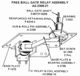
Looks very similar but doesn't look like the BEARING is mounted on the BASE PLATE?
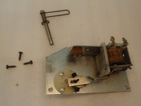
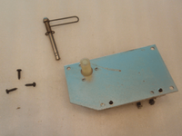
This is what the mechanism on MR & MRS PAC-MAN looks like (this isn't mine). Notice that this mechanism has a plastic plate that can operate one or more stacked leaf switches. I don't know why but the MMPM mech seems to only have half switch with just a single leaf/blade:


Did you reflow the solder on the connector for J5..?
So you've established that the Base of Q17 gets the signal and that when activated it fires the coil (using either the collector or emitter depending on the transistor). The problem is the other transistor leg which is the activation path that will eventually go to earth and which you should be able to follow the trace on the board.
So you've established that the Base of Q17 gets the signal and that when activated it fires the coil (using either the collector or emitter depending on the transistor). The problem is the other transistor leg which is the activation path that will eventually go to earth and which you should be able to follow the trace on the board.
Last edited:
A-ha! Good plan! Except... GOLD BALL has a different board! It uses the AS-2518-147 HV/LAMP/SOLENOID DRIVER COMBO MODULE that was only used in GOLD BALL and GRAND SLAM. It doesn't have enough solenoid channels and it uses a dual-phase AC supply to double the number of Lamp channels it can handle:why not see if goldballs SDB works in pacman and visa-versa,it should tell you if it's a board or wiring fault?
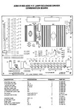
If VECTOR was here I could swap that SDB, but @astyy has it for "reference purposes" for his VECTOR project rebuild
Oh wait... I could use the one from PARAGON... if only I could find it under all the junk...
It's a weedy sort of mechanism, Peter. There was still one of these games in use when I was a serviceman, at the end of the 80's. I found that adjustment of the contact blade was helpful in getting the gate to return properly.
Is the base resistor for the drive transistor alright? 330 Ohms, 1/2 W as I recall. A tricky one like this I tackled turned out to be caused by this resistor being open-circuit; it broke apart during removal.
Is the base resistor for the drive transistor alright? 330 Ohms, 1/2 W as I recall. A tricky one like this I tackled turned out to be caused by this resistor being open-circuit; it broke apart during removal.
I've found the SOLENOID DRIVER BOARD from PARAGON! If I get 5 minutes away from all the ****ing domestic chores, cleaning, washing up, laundry, lawn mowing, etc., I'll stick it in and see what happens! 
Peter
I have had problems with weedy mechs like this before, on my TZ and Funhouse. With the inevitable wear they receive over time, the damned things can stick. I actually filed, then sanded, the roll pin to remove much of the "lip" that exists between the two ends of the metal as they meet to form the cylinder
I have had problems with weedy mechs like this before, on my TZ and Funhouse. With the inevitable wear they receive over time, the damned things can stick. I actually filed, then sanded, the roll pin to remove much of the "lip" that exists between the two ends of the metal as they meet to form the cylinder
23-October-2016
MORE SOLENOID WOES...
I also swapped in my AS-2518-22 SOLENOID DRIVER BOARD from my PARAGON hoping that I'd be able to conclusively rule out problems with the same board that came with MMPM, but when I powered it on I got the red OVERLOAD warning LED on the ALLTEK MPU lit up. I checked the output of the +5V regulator and it was 0.2V Oh, dear.
So, after double-checking all the tracks, pins and components for continuity, shorts or failure that I could manage on the bench, I put the old board back in. I then set the MPU in Solenoid Test Mode and started watching all the solenoids. Here are the test numbers displayed during Solenoid Test Mode:
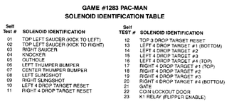
And here's the list of driving transistors:
So, everything is fine for Self Test #01 to #05 (single coil per Q transister) but then as it goes through #06 to #12 (default coil when SOLENOID EXPANDER is OFF) I notice that other coils like the little drop-target resets start to jitter just a tiny bit. #13 is fine as this is just a single coil for Q8, but then for #14 to #20 (expansion coil when SOLENOID EXPANDER is ON) things start to get really weird. One, two, then three drop-target reset coils start to fire on the left-hand bank, and two coils and then 4 reset coils fire on the right-hand drop-target bank! The main drop-target reset coils are also jittery just a tiny bit here and there.
WTF?
As a quick test I swap the power cables over on pins 5 and 7 on the SOLENOID EXPANDER BOARD so that by default the expansion coils get fired. This means I can ground the metal tabs on the Q transistors to test them manually. Even doing this I've got drop-target coils jittering all over the place!
I think I've got a problem with the playfield loom. The lamp holders for the P-A-C M-A-N inserts are frightfully close the drop-target coil logs so maybe there's a short.
Or a crappy IDC header Actually all IDC headers are crap. The sooner I re-pin with Molex KK Trifurcons the better.
MORE SOLENOID WOES...
The gate coil is definitely working. If I ground the tab of transistor Q17 it fires and closes the mech firmly. Also, I ground Pin 10 on the CA3081 transistor array (U4) that drives Q17 and that also fired the coil, so the A3 SOLENOID DRIVER BOARD is not the problem.Might you have coil burn out ?
I also swapped in my AS-2518-22 SOLENOID DRIVER BOARD from my PARAGON hoping that I'd be able to conclusively rule out problems with the same board that came with MMPM, but when I powered it on I got the red OVERLOAD warning LED on the ALLTEK MPU lit up. I checked the output of the +5V regulator and it was 0.2V
So, after double-checking all the tracks, pins and components for continuity, shorts or failure that I could manage on the bench, I put the old board back in. I then set the MPU in Solenoid Test Mode and started watching all the solenoids. Here are the test numbers displayed during Solenoid Test Mode:

And here's the list of driving transistors:
Code:
Q#  Coil                              CA3081           74L154
                                      Pre-Driver IC    Decoder
                                      Chip,Base,Coll   ABCD/Pin
--- --------------------------------- ---------------- --------
Q1  Top Left Saucer - Kick Right      U1, 16, 1        0001/2
Q2  Top Left Saucer - Kick Left       U1,  3, 2        0000/1
Q3  Knocker                           U1,  6, 4        0101/6
Q4  Outhole Kicker                    U1,  8, 7        0110/7
Q5  Right Saucer                      U1, 13, 14       0010/3
Q6  -                                 U1, 11, 12       0011/4
Q7  -                                 U1, 10, 9        0100/5
Q8  Left 4 Drop Target #1 (Bottom)    U3, 16, 1        0111/8
Q9  Left Slingshot                    U3,  3, 2        1010/11
    Left 4 Drop Target #4 (Top)
Q10 Right Slingshot                   U3,  8, 7        1011/13
    Right 4 Drop Target #1 (Top)
Q11 Right 4 Drop Target Reset         U3,  6, 4        1101/15
    Right 4 Drop Target #3
Q12 Left 4 Drop Target Reset          U3, 10, 9        1100/14
    Right 4 Drop Target #2
Q13 Left Pop Bumper                   U3, 11, 12       1000/9
    Left 4 Drop Target #2
Q14 Center Pop Bumper                 U3, 13, 14       1001/10
    Left 4 Drop Target #3
Q15 Flipper Enable Relay              U4,  3, 2        CONT.PB6
Q16 Top 3 Drop Target Reset           U4,  8, 7        1110/16
    Right 4 Drop Target #4 (Bottom)
Q17 Gate                              U4, 10, 9        CONT.PB4
Q18 -                                 U4, 11, 12       CONT.PB7
Q19 Coin Lockout                      U4, 13, 14       CONT.PB5
So, everything is fine for Self Test #01 to #05 (single coil per Q transister) but then as it goes through #06 to #12 (default coil when SOLENOID EXPANDER is OFF) I notice that other coils like the little drop-target resets start to jitter just a tiny bit. #13 is fine as this is just a single coil for Q8, but then for #14 to #20 (expansion coil when SOLENOID EXPANDER is ON) things start to get really weird. One, two, then three drop-target reset coils start to fire on the left-hand bank, and two coils and then 4 reset coils fire on the right-hand drop-target bank! The main drop-target reset coils are also jittery just a tiny bit here and there.
WTF?
As a quick test I swap the power cables over on pins 5 and 7 on the SOLENOID EXPANDER BOARD so that by default the expansion coils get fired. This means I can ground the metal tabs on the Q transistors to test them manually. Even doing this I've got drop-target coils jittering all over the place!
I think I've got a problem with the playfield loom. The lamp holders for the P-A-C M-A-N inserts are frightfully close the drop-target coil logs so maybe there's a short.
Or a crappy IDC header
It may be to do with the solenoid expander board, I am on hols so can't look at my games. But from memory I had some shananigans on both vector and fathom because of the way this board operates. I swapped the boards between the games so I could see that the two of them both worked
Vector - A bridge rectifier was on the way out so I had intermittent problems on some solenoids for a day before the BR on the (5v?) power board in the base of the cab died during the practice session at a meeting. Because of this the light board in Vector was only getting half the volts it needed. This light board activated the relay on the solenoid expander board and there wasn't enough power to click the relay. Dave and Terry identified this and we got it going again by stripping a BR off a spare wpc board I had!, and replacing the dead one in the game
Fathom - The solenoids that are served via the solenoid expander need diodes (like flipper coils). This contrasts with the same mechs powered by the same coils on games that do not have the expander board that do not have diodes on. Indeed on the same game you may find identical mechs, one has no diode but the other does as it is served by the solenoid expander board.
So if you have a coil lock on, and burn out .......If that coil is on the solenoid expander circuit it should have a diode on it, the repairman misses this, regular (no diode) coil goes back in - chaos. You get all manner of multiple coil misfirings, multiple coil tremors, half hearted firing. One correcty inserted diode on the relevant coil can then cure all these symptoms
Last edited:
@DRD I think you might have got to the nub of the problem. I'm confident there's nothing wrong with the SOLENOID DRIVER board. I think I've got one or more dead or missing coil diodes, or a nasty short in the playfield loom. I can't see any other reason why I'd have mutilple coils operating when I manually ground to test.
Time to check all the coils and their diodes...
Time to check all the coils and their diodes...

