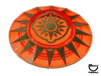
Quiet day?!Did a bit more research via IPDB. I looked at all the solid-state games released by Bally between 1980 and 1988. The change from what I will call "classic star" pop bumper covers to "ring and cap" covers appears to have ended with FLASH GORDON (custom red translucent) and started with EIGHT BALL DELUXE (custom translucent orange):
"CLASSIC STAR" one-piece cover with PARAGON image:
View attachment 37562
FLASH GORDON, the last "classic star" but in translucent red and with custom centre art:
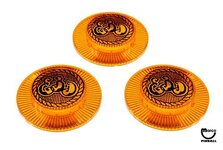
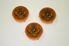
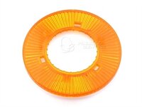
EIGHT BALL DELUXE, the first 2-part "ring and cap" covers in translucent orange with custom EBD logo:
EBD caps in translucent orange:
Translucent orange ring:
I went through all the other releases up to the final game under the Bally name, BLACKWATER 100. Those marked * have custom logos printed on the cap:
1981-04 Eight Ball Deluxe 400 Opaque White* then all Translucent Orange*
1981-06 Embryon Translucent Blue*
1981-06 Fireball II Translucent Red*
1981-08 Fathom Translucent Blue*
1981-09 Medusa Translucent Red*
1981-10 Centaur Translucent Red
1981-12 Elektra No pop bumpers
1982-02 Vector 1 pop bumper but no cap
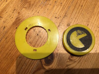
1982-05 Mr. & Mrs. Pac-Man Pinball Opaque Yellow*
1982-08 Speakeasy Translucent Orange*
1982-08 Speakeasy 4 Translucent Orange*
1982-08 Spectrum No pop bumpers
1982-10 Baby Pac-Man No pop bumpers
1982-10 Eight Ball Deluxe Limited Edition Translucent Orange*
1982-11 BMX No pop bumpers
1983-03 Grand Slam Opaque White*
1983-06 Centaur II Translucent Red
1983-10 Gold Ball Translucent Orange*
1984 Eight Ball Deluxe Translucent Orange*
1984-01 Granny and the Gators No pop bumpers
1984-02 X's & O's Translucent Orange*
1984-03 Kings of Steel Translucent Orange*
1984-07 Black Pyramid Translucent Orange (1000 WHEN LIT 3000 WHEN FLASHING)
1984-10 Spy Hunter Translucent Orange*
1985-02 Fireball Classic Translucent Orange* ( 1000 WHEN LIT 3000 WHEN FLASHING + MEDUSA HEAD)
1985-05 Cybernaut Translucent Orange (ring only)
1985-08 Eight Ball Champ Translucent Red*
1985-11 Beat the Clock Translucent Blue*
1986-03 Lady Luck Translucent Orange
1986-06 Black Belt Translucent Red*
1986-06 Motordome Translucent Orange (1000 WHEN LIT 3000 WHEN FLASHING)
1986-09 Special Force Custom Jungle Huts
1986-11 Strange Science Translucent Orange*
1987-03 City Slicker Translucent Blue*
1987-04 Hardbody No pop bumpers
1987-05 Party Animal Translucent Orange?
1987-08 Heavy Metal Meltdown Translucent Orange
1987-10 Dungeons & Dragons Translucent Orange
1988-01 Escape from the Lost World Translucent Red
1988-03 Blackwater 100 No pop bumpers
So, what do we notice? Orange wins the day with 18 games, red with 7 and blue with 4, all translucent. Opaque white crops up just twice but in limited numbers on the first 400 EBDs and 1,000 GRAND SLAMs. Opaque yellow? Completely unique to MPMM. Interesting that all games except CENTAUR I and II up until 1986's LADY LUCK had custom printed caps, but thereafter it was more likely that games had plain rather custom caps (last 4 games with caps all plain) - yet more cost cutting during the downfall of Bally? Three games shared a printed cap with the instruction "1000 WHEN LIT 3000 WHEN FLASHING".
Pinball info
You are using an out of date browser. It may not display this or other websites correctly.
You should upgrade or use an alternative browser.
You should upgrade or use an alternative browser.
In Progress Lost in the PAC MAZE... Another Obsessive Restoration
- Thread starter Nedreud
- Start date
-
- Tags
- bally mpmm project restoration
I usually do!Could you hand-finish it to get a better finish?
Seriously tho gonna follow this tread with interest, love it when a man's on a mission!
I'm OCD central once I get stuck into something. I find I can't sleep or keep waking suddenly realising what the solution to a particular problem is. I have to admit to feeling a little guilty that I've got scmucked into another pin instead of getting back to PARAGON. Still... plenty to do all round. Really I need to finish insulating and panelling the summerhouse so it's a nicer place to work and play. It always looks such a dump in my photos hence why most are close ups!love it when a man's on a mission!
19-October-2016
TESTING TRANSFORMER & AS-2518-54 PSU MODULE
Ok, time to start working out what's wrong with this sucker. No electrical system is going to work unless you have a solid power supply. First things first, fresh batteries in my Precision Gold WG020 Multimeter. Got this cheap as chips from Maplin. It's got a big display, grippy rubber case to take the inevitable knocks and drops, and measure Volts up to 1,000 DC and 750 AC. It also does Impedance, Frequency, Duty, Resistance, Capacitance, NPN/PNP transistor testing and current up to 10A. Decided to treat it to a quality battery
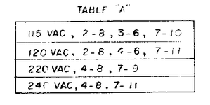
Next I double-checked that the INPUT voltage selector jumpers were correct for 240 VAC in the UK. This is done by setting either 2 or 3 jumper wires between various points in the J1 connector that is mounted on the main PSU panel in the bottom of the cabinet. This is also where the F1 3A Slow Blow fuse is mounted (checked that too!) and is fed by the pair of wires from the ON/OFF switch on the underside of the cabinet. For UK 240 VAC two jumpers between pins 4-8 and 7-11 have to be set, which they were:
First tests are to make sure the transformer is kicking out the correct supply voltages. Pinball machines have multi-tapped windings on both the input and output, meaning that they can be configured for the different supply voltages around the world and generate a set selection of different output voltages. To check the outputs remove connectors J5 and J6 from the AS-2518-54 module. Then poke your test leads into the appropriate holes in the connectors.
Right, appropriately large safety message posted. You have been warned. I like to wear gloves and switch off and disconnect the mains. It's time consuming but so much better than being electrocuted. Here are the results:
J5 Pin 1 or 4 YELLOW and Pin 7 or 8 YELLOW/BLACK 6.5 VAC
Test reading: 6.5 VAC
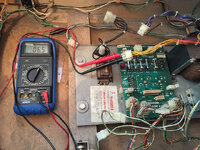
J5 Pin 2 RED and Pin 3 RED 170 VAC
Test reading: 179.3 VAC
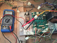
J5 Pin 2 GREEN and Pin 3 ORANGE 49 VAC
Test reading: 49.5 VAC
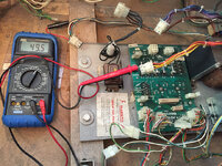
J6 Pin 2 PURPLE and Pin 3 PURPLE/BLACK 9.4 VAC
Test reading: 9.5 VAC
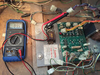
J6 Pin 2 BLUE and Pin 3 BLUE 14.2 VAC
Test reading: 14.0 VAC
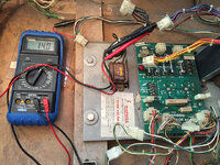
All of these readings are well within tolerance. You don't expect exactly the same values as the schematic. Transformers have a little natural variance. Also, the output voltages can be a little different when not under load, just like during this test as everything is disconnected. Basically what I've established here is that the transformer looks good and isn't total toast. Doesn't prove it's perfect as it could still go wonky under load but we're off to a good start!
Next, it's time to test the performance of the AS-2518-54 rectifier module. This board is very simple and is basically 5 separate circuits in one board with fuses with AC to DC rectification on 4 circuits. GI or General Illumination is run on 6.5 VAC so no rectifier is needed.
During testing the output connectors J1, J2, J3 and J4 are removed - we don't want any faults or shorts further down the line interfering. Alligator clips were then added to the test probes so that they can be easily clipped onto the test points (TP).
TP1 6.5 VDC SW.IL. (SWITCHED ILLUMINATION)
Test reading: 7.36 VDC
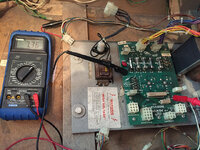
TP2 +230 VDC (UNREGULATED 190)
Test reading: 173 VDC
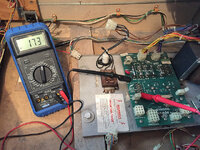
TP3 11.9 VDC (UNREGULATED +5V)
Test reading: 34.2 VDC using GND
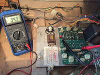
Test reading: 11.3 VDC using base of CR6
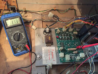
TP4 6.5 VAC GI (GENERAL ILLUMINATION)
Test reading: 6.5 VAC
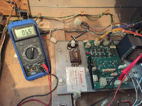
TP5 +43 VDC (SOLENOIDS)
Test reading: 43.4 VAC
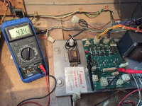
Those of you still paying attention and not scrolling past all the seemingly identical photos will have noticed that I've got a dodgy reading on TP3. I should be getting 11.9 VDC but it's reading just over 34 VDC! But the really strange thing is after testing the input and output voltages on the bridge rectifier formed by diodes CR5, CR6, CR7 and CR8 I noticed that the output measured at TP3 was 11.3 VDC if I used the base of CR6 as the ground point. This is weird because the base of CR6 should be connected to the GND test point on the board!
Here's the relevant part of the schematic showing where the voltages were measured:
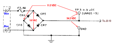
We know that 14.0 VAC is on the blue wires from J6 and I measured that directly across the BR (Bridge Rectifier) formed by diodes CR5/6/7/8. I also checked the output of the BR directly by clipping probes onto the base of CR6 and head of CR7. And as tested earlier there's 11.3 VDC between the base of CR6 and TP3. But when I move the black probe from CR6 to the GND test point I get 34.2 VDC. There's a leak somewhere!
Next task will be to remove the board from the chassis and inspect it for and shorts, e.g., bits of solder. Have to admit at this stage I'm a bit flummoxed
TESTING TRANSFORMER & AS-2518-54 PSU MODULE
Ok, time to start working out what's wrong with this sucker. No electrical system is going to work unless you have a solid power supply. First things first, fresh batteries in my Precision Gold WG020 Multimeter. Got this cheap as chips from Maplin. It's got a big display, grippy rubber case to take the inevitable knocks and drops, and measure Volts up to 1,000 DC and 750 AC. It also does Impedance, Frequency, Duty, Resistance, Capacitance, NPN/PNP transistor testing and current up to 10A. Decided to treat it to a quality battery

Next I double-checked that the INPUT voltage selector jumpers were correct for 240 VAC in the UK. This is done by setting either 2 or 3 jumper wires between various points in the J1 connector that is mounted on the main PSU panel in the bottom of the cabinet. This is also where the F1 3A Slow Blow fuse is mounted (checked that too!) and is fed by the pair of wires from the ON/OFF switch on the underside of the cabinet. For UK 240 VAC two jumpers between pins 4-8 and 7-11 have to be set, which they were:

First tests are to make sure the transformer is kicking out the correct supply voltages. Pinball machines have multi-tapped windings on both the input and output, meaning that they can be configured for the different supply voltages around the world and generate a set selection of different output voltages. To check the outputs remove connectors J5 and J6 from the AS-2518-54 module. Then poke your test leads into the appropriate holes in the connectors.
!!! PLEASE REMEMBER YOU ARE DEALING WITH LIVE MAINS ELECTRICITY !!!
!!! IF YOU DON'T KNOW WHAT YOU ARE DOING YOU CAN DIE !!!
!!! IF YOU DO KNOW WHAT YOU ARE DOING YOU CAN STILL DIE !!!
!!! PLEASE TAKE APPROPRIATE PRECAUTIONS - EITHER DISCONNECT THE MAINS BETWEEN EACH TEST OR USE HEAVY DUTY GLOVES !!!
!!! IF YOU DON'T KNOW WHAT YOU ARE DOING YOU CAN DIE !!!
!!! IF YOU DO KNOW WHAT YOU ARE DOING YOU CAN STILL DIE !!!
!!! PLEASE TAKE APPROPRIATE PRECAUTIONS - EITHER DISCONNECT THE MAINS BETWEEN EACH TEST OR USE HEAVY DUTY GLOVES !!!
Right, appropriately large safety message posted. You have been warned. I like to wear gloves and switch off and disconnect the mains. It's time consuming but so much better than being electrocuted. Here are the results:
J5 Pin 1 or 4 YELLOW and Pin 7 or 8 YELLOW/BLACK 6.5 VAC
Test reading: 6.5 VAC

J5 Pin 2 RED and Pin 3 RED 170 VAC
Test reading: 179.3 VAC

J5 Pin 2 GREEN and Pin 3 ORANGE 49 VAC
Test reading: 49.5 VAC

J6 Pin 2 PURPLE and Pin 3 PURPLE/BLACK 9.4 VAC
Test reading: 9.5 VAC

J6 Pin 2 BLUE and Pin 3 BLUE 14.2 VAC
Test reading: 14.0 VAC

All of these readings are well within tolerance. You don't expect exactly the same values as the schematic. Transformers have a little natural variance. Also, the output voltages can be a little different when not under load, just like during this test as everything is disconnected. Basically what I've established here is that the transformer looks good and isn't total toast. Doesn't prove it's perfect as it could still go wonky under load but we're off to a good start!
Next, it's time to test the performance of the AS-2518-54 rectifier module. This board is very simple and is basically 5 separate circuits in one board with fuses with AC to DC rectification on 4 circuits. GI or General Illumination is run on 6.5 VAC so no rectifier is needed.
During testing the output connectors J1, J2, J3 and J4 are removed - we don't want any faults or shorts further down the line interfering. Alligator clips were then added to the test probes so that they can be easily clipped onto the test points (TP).
TP1 6.5 VDC SW.IL. (SWITCHED ILLUMINATION)
Test reading: 7.36 VDC

TP2 +230 VDC (UNREGULATED 190)
Test reading: 173 VDC

TP3 11.9 VDC (UNREGULATED +5V)
Test reading: 34.2 VDC using GND

Test reading: 11.3 VDC using base of CR6

TP4 6.5 VAC GI (GENERAL ILLUMINATION)
Test reading: 6.5 VAC

TP5 +43 VDC (SOLENOIDS)
Test reading: 43.4 VAC

Those of you still paying attention and not scrolling past all the seemingly identical photos will have noticed that I've got a dodgy reading on TP3. I should be getting 11.9 VDC but it's reading just over 34 VDC! But the really strange thing is after testing the input and output voltages on the bridge rectifier formed by diodes CR5, CR6, CR7 and CR8 I noticed that the output measured at TP3 was 11.3 VDC if I used the base of CR6 as the ground point. This is weird because the base of CR6 should be connected to the GND test point on the board!
Here's the relevant part of the schematic showing where the voltages were measured:

We know that 14.0 VAC is on the blue wires from J6 and I measured that directly across the BR (Bridge Rectifier) formed by diodes CR5/6/7/8. I also checked the output of the BR directly by clipping probes onto the base of CR6 and head of CR7. And as tested earlier there's 11.3 VDC between the base of CR6 and TP3. But when I move the black probe from CR6 to the GND test point I get 34.2 VDC. There's a leak somewhere!
Next task will be to remove the board from the chassis and inspect it for and shorts, e.g., bits of solder. Have to admit at this stage I'm a bit flummoxed
Ronsplooter is a bell end
One more test. Removed board from chassis - everything looks sound. Cross-referencing the schematic and components CR5 and CR6 are labelled the wrong way round:
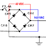
Removed all fuses except F3 and only reconnected power input connector J6. Checked voltages again. Definitely 14.0 VAC on the input to the BR, but now getting as high as +43 VDC across the output! Think I've got some some duff 3A diodes!

Removed all fuses except F3 and only reconnected power input connector J6. Checked voltages again. Definitely 14.0 VAC on the input to the BR, but now getting as high as +43 VDC across the output! Think I've got some some duff 3A diodes!
You're a c*nt cooldan
One more test. Removed board from chassis - everything looks sound. Cross-referencing the schematic and components CR5 and CR6 are labelled the wrong way round:
View attachment 37589
Removed all fuses except F3 and only reconnected power input connector J6. Checked voltages again. Definitely 14.0 VAC on the input to the BR, but now getting as high as +43 VDC across the output! Think I've got some some duff 3A diodes!
What do the diodes do in this situation @nedrued (also, what does a diode do fullstop)? In terms more simple than 'Electronics for Idiots' if that is even possible
- Joined
- Jul 21, 2011
- Messages
- 2,525
Language, Timothy!You're a c*nt cooldan
Have you seen this thread from a Pinside ?
https://pinside.com/pinball/forum/topic/looking-for-mrms-pacman-pinball-pop-bumper-caps?responsive=0
https://pinside.com/pinball/forum/topic/looking-for-mrms-pacman-pinball-pop-bumper-caps?responsive=0
In basic basic terms a diode is a one-way valve for electricity. It gets more complex as diodes are semi-conductors so they have specific electrical properties that allow them to be used to do all sorts of clever stuff, but for this situation of turning AC (Alternating Current) in to DC (Direct Current) you can just pretend they're one way gates.What do the diodes do in this situation @nedrued (also, what does a diode do fullstop)? In terms more simple than 'Electronics for Idiots' if that is even possible
So... what is AC you might ask? The electricity that comes out of the power sockets in your house is AC. It's 240 Volts AC (actually it's 230 VAC since 2003 but there's a tolerance that means it can be as low as 206 or high as 253). But this value is the average over time because what's really happening is the voltage is starting from zero and rises up to a peak of +340V then drops back down to zero and then continues to drop down to negative -340 V and finally back up to zero again. And it does this 50 times a second hence the 50 Hz (Hertz) frequency you may know about. Essentially the voltage is going back and forth - or alternating.
Why? Well, distributing lots of power over large distances like the National Grid is more efficient using AC than DC. And then using it to power light bulbs and kettles is easy because they're simple things that just get hot - you use AC or DC.
But low power electronic devices need DC because circuits based on DC are simpler to design. Batteries supply DC. They have to be fitted the right way round because the (+) and (-) doesn't change. So there's a need to convert AC to DC if you want to power electronic devices from the mains. The transformer is the first part as this usually reduces the AC voltage to something more usable. Say 240 VAC down to 12 VAC. It's still AC and it's still going positive and negative 50 times a seconds, but voltage is now much more usable.
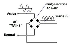
Next feed the AC through a single diode. A diode will only let electricity flow through it one way. It will let the positive voltage through one way but not the negative voltage back the other. This would make the 12 VAC look like this:

But half the wave is missing I hear you cry! And you're right. It's now DC because the current only flows in one direction but it's a bit gappy. The next step is to arrange 4 diodes in a "bridge" so that whatever direction the current is flowing it's "joined" back up to the output:

Yay! Now all the bumps are on the top!
This still isn't ideal as it's still going up and down between 0 and some positive voltage. There are lots of different ways of "smoothing" out the bumps to get closer to an ideally completely flat and stable DC voltage. The simplest solution is to add a "smoothing" capacitor across the output. This charges up when the voltage is high and then slowly discharges when the voltage drops filling in the gaps. There's a little bit of "ripple" but for most applications this isn't important.
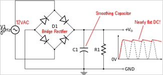
For pinball, this is just fine for the 6.5 VDC switched illumination but isn't good enough for the precisely stable +5VDC required by the processor in the controller board. For that, an additional voltage regulator circuit is needed.
Hopefully that helps? Either that or you've fallen asleep
This was exactly what I found. But it's so hard to find the opaque yellow caps and rings as they were only ever made for PAC-MAN (as far as I know). Even Steve Young's Pinball Resource is sold out of the rings although they do have the caps: http://www.pbresource.com/pfbumper.htm (search for BLY-C1014Y on the page).Have you seen this thread from a Pinside ?
https://pinside.com/pinball/forum/topic/looking-for-mrms-pacman-pinball-pop-bumper-caps?responsive=0
Problem with PBR is that they're difficult to deal with outside the US. They want cash in dollars or a US bank backed cheque. And their international postage chargs are usually horrific
Fantastic stuff Peter, keep it coming. You're a natural teacher.
LOL! I've got 2 sets just like that! Both with missing lugs and melted with superglueIs this any use?
The ring is pitted (from previous superglue) and all three lugs are broken off the cap but with a little hot glue it will look almost perfect.
IMG_2210 by Dave2084, on Flickr
You beauty! And only $3.50 each. So if I get 2 of these from BAA and 2 plain caps from PBR ($3.00 each) that's a grand total of $13.00. Very reasonable.
What's the betting that with shipping from two US-based merchants the grand total comes to more than $80? And then I'd get hit with import duty and the Royal Mail's "handling fee"?
Time to sweet talk a couple of US friends...
Not found anyone anywhere selling opaque white caps or rings at all. Only used on 2 games: the first 400 EIGHT BALL DELUXE and 1,000 GRAND SLAMS.Could you get white and try dyeing them with food dye ?
You beauty! And only $3.50 each. So if I get 2 of these from BAA and 2 plain caps from PBR ($3.00 each) that's a grand total of $13.00. Very reasonable.
What's the betting that with shipping from two US-based merchants the grand total comes to more than $80? And then I'd get hit with import duty and the Royal Mail's "handling fee"?
Time to sweet talk a couple of US friends...
BAA Quoted me shipping of $40!
I removed the CR5-8 diodes from the board this evening and tested with the multimeter. All have a forward-biased voltage drop of at least 0.480 up to about 0.540, and all read OL when reverse-biased. This means they all test good.
So the mystery deepens... going to get some 1N5404 replacements tomorrow but this will involve visiting at least two of my local Maplin stores as none of them stock any more than 3 at a time
I might have to strip the entire board just be sure there's nothing else dodgy going on. At least if I do that I'll be able put the PCB in the flat-bed scanner so I can do some remakes at a later date
In basic basic terms a diode is a one-way valve for electricity. It gets more complex as diodes are semi-conductors so they have specific electrical properties that allow them to be used to do all sorts of clever stuff, but for this situation of turning AC (Alternating Current) in to DC (Direct Current) you can just pretend they're one way gates.
So... what is AC you might ask? The electricity that comes out of the power sockets in your house is AC. It's 240 Volts AC (actually it's 230 VAC since 2003 but there's a tolerance that means it can be as low as 206 or high as 253). But this value is the average over time because what's really happening is the voltage is starting from zero and rises up to a peak of +340V then drops back down to zero and then continues to drop down to negative -340 V and finally back up to zero again. And it does this 50 times a second hence the 50 Hz (Hertz) frequency you may know about. Essentially the voltage is going back and forth - or alternating.
Why? Well, distributing lots of power over large distances like the National Grid is more efficient using AC than DC. And then using it to power light bulbs and kettles is easy because they're simple things that just get hot - you use AC or DC.
But low power electronic devices need DC because circuits based on DC are simpler to design. Batteries supply DC. They have to be fitted the right way round because the (+) and (-) doesn't change. So there's a need to convert AC to DC if you want to power electronic devices from the mains. The transformer is the first part as this usually reduces the AC voltage to something more usable. Say 240 VAC down to 12 VAC. It's still AC and it's still going positive and negative 50 times a seconds, but voltage is now much more usable.
Next feed the AC through a single diode. A diode will only let electricity flow through it one way. It will let the positive voltage through one way but not the negative voltage back the other. This would make the 12 VAC look like this:
View attachment 37600
But half the wave is missing I hear you cry! And you're right. It's now DC because the current only flows in one direction but it's a bit gappy. The next step is to arrange 4 diodes in a "bridge" so that whatever direction the current is flowing it's "joined" back up to the output:
View attachment 37601
Yay! Now all the bumps are on the top!
This still isn't ideal as it's still going up and down between 0 and some positive voltage. There are lots of different ways of "smoothing" out the bumps to get closer to an ideally completely flat and stable DC voltage. The simplest solution is to add a "smoothing" capacitor across the output. This charges up when the voltage is high and then slowly discharges when the voltage drops filling in the gaps. There's a little bit of "ripple" but for most applications this isn't important.
View attachment 37603
For pinball, this is just fine for the 6.5 VDC switched illumination but isn't good enough for the precisely stable +5VDC required by the processor in the controller board. For that, an additional voltage regulator circuit is needed.
Hopefully that helps? Either that or you've fallen asleep
That all makes sense and was a great explanation
I might have to strip the entire board just be sure there's nothing else dodgy going on. At least if I do that I'll be able put the PCB in the flat-bed scanner so I can do some remakes at a later date
Have you tested your earth resistance from the leg of the BR to the earth in the cabinet? I'd do that first...

20-October-2016
AS-1518-54 POWER MODULE OVERHAUL
After a very successful trip to Maplin (you don't hear someone say that very often) I got some new 1N5404 and 1N4007 diodes. Their website said they only had three 1N5404 in stock in Woking so I was going to have to go to Guildford or Farnborough as well (nowhere had more than 3). I joked with the assistant about how different Maplin was when I worked there 20 years ago but it was always worth checking the back of component drawers in the stock room, or the adjacent drawers. To my surprise the guy said he'd go back and double-check and what do you know? He found a fourth diode in the back of the drawer! Result!
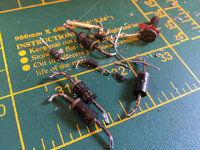
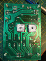
I'd already pulled the CR5-8 diodes (type V330 50V 3A) yesterday so it was a simple job to fit the new 1N5404 diodes which are 400V 3A equivalents. I've had problems on other boards with the CR1-4 diodes that form the bridge rectifier for the +190V displays so I replaced the old 1N4004 with 1N4007 diodes. Quite pleased I did as one of them just crumbled to pieces whilst removing it:
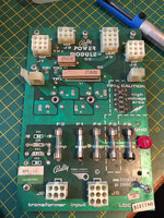
Other than being dirty the board itself looks good. I did clean the ends of the fuse and inside the fuse holders with 2500 grit wet and dry paper:
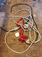
After @Moonraker's comment about checking the ground, I decided I should make sure there were no Gremlins in the mains power cable. The continuity between the earth pin and the cabinet was diabolical, very intermittent, so pulled the old one, which had been spliced in the middle to make it longer:
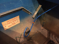
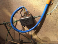
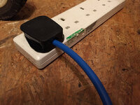
Whilst soldering the lovely new blue cable (same as the one I fitted to GOLD BALL) onto the line filter inside the cabinet I noticed that the MOV (Metal-Oxide Varistor) is missing (notice the adjacent factory fitted information card). Whilst this isn't needed for the machine to work it provides protection against surges that might come down the mains line, so will need to add one of these to the shopping list. After fitting the cable I checked earth continuity around the entire cabinet and it's good everywhere (rails, lockdown bar, coin door, earth braid, power supply chassis, legs, backbox) except the backglass lift channel, so will need to clean things up there too.
Refitted the AS-2518-54 POWER MODULE back into the bottom of the cabinet, plugged in all the connectors but disconnected J3 on the A3 SOLENOID DRIVER MODULE as this is the power input connector for the +5V and +190V regulators. Clipped multimeter onto the GND and TP3 test points and turned on the power... BINGO! 14VDC. Maybe a volt or two higher than the ideal but fine for feeding the LM323K 5V regulator circuit.
At this point I reconnected A3-J3 and checked the output of the +5V regulator circuit across the GND and TP1 test points on this board: the reading was +5.35V which is 0.1V higher than the recommneded maximum, but worryingly there was an AC voltage of 0.255! That's a quarter volt of ripple which is WAY beyond the tolerance of no more than 150mV of ripple for powering the MPU. I think this is what's causing the ALLTEK MPU to keep rebooting repeatedly and generally actt strange.
Smoothing for the +5V supply is handled by the large 11,000uF C23 capacitor, except it's been replaced with this suspect ****ty hack:
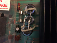
Looking closely that's three 2,200uF capacitors in parallel giving a total capacitance of 6,600uF which is just half of the specified 11,700uF on the schematic! I don't have any new caps of this size to hand but did have a spare from an old board that tested just fine on the ESR meter, so I popped that in temporarily (piece of paper was just to prevent shorting on the Q transistors whilst testing):
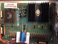
Output voltage now a perfect +5.25V with less than 25mV of ripple. Sweet! Switch on again and this time I get 7 flashes out of the ALLTEK and then it sits there doing nothing but it's no longer rebooting over and over again. Another step forwards...
So what's preventing the final 8th flash? Time to RTFM. Checking the board I have a Revision K ULTIMATE MPU: http://www.allteksystems.com/pdfs/New_Complete_Manual_Ver_K.pdf. The troubleshooting section suggests that this problem can be caused by the +43V solenoid power not reaching the MPU. I know I've got +43VDC coming out of the PSU and the game manual schematics show that this is fed directly to the MPU and is not part of the solenoid power that passes through the under-playfield fuse (which I know is blown). So I put the multimeter on the ALLTEK across GND and TP7 - definitely no +43VDC:
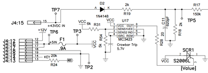
Whilst doing this I end up knocking connector J4 on the ALLTEK and all the LEDs flash and it reboots again. Hello... that's a dodgy connector. I pull off J4, which is an IDC type connector, and sure enough the wire on Pin 15 has fallen off! That explains the missing +43VDC!
Let me just state this again clearly so it's on the record: I HATE IDC CONNECTORS. THEY'RE SH*T.
I wonder if you can guess what happened next...?
AS-1518-54 POWER MODULE OVERHAUL
After a very successful trip to Maplin (you don't hear someone say that very often) I got some new 1N5404 and 1N4007 diodes. Their website said they only had three 1N5404 in stock in Woking so I was going to have to go to Guildford or Farnborough as well (nowhere had more than 3). I joked with the assistant about how different Maplin was when I worked there 20 years ago but it was always worth checking the back of component drawers in the stock room, or the adjacent drawers. To my surprise the guy said he'd go back and double-check and what do you know? He found a fourth diode in the back of the drawer! Result!
I'd already pulled the CR5-8 diodes (type V330 50V 3A) yesterday so it was a simple job to fit the new 1N5404 diodes which are 400V 3A equivalents. I've had problems on other boards with the CR1-4 diodes that form the bridge rectifier for the +190V displays so I replaced the old 1N4004 with 1N4007 diodes. Quite pleased I did as one of them just crumbled to pieces whilst removing it:

Other than being dirty the board itself looks good. I did clean the ends of the fuse and inside the fuse holders with 2500 grit wet and dry paper:


After @Moonraker's comment about checking the ground, I decided I should make sure there were no Gremlins in the mains power cable. The continuity between the earth pin and the cabinet was diabolical, very intermittent, so pulled the old one, which had been spliced in the middle to make it longer:

Whilst soldering the lovely new blue cable (same as the one I fitted to GOLD BALL) onto the line filter inside the cabinet I noticed that the MOV (Metal-Oxide Varistor) is missing (notice the adjacent factory fitted information card). Whilst this isn't needed for the machine to work it provides protection against surges that might come down the mains line, so will need to add one of these to the shopping list. After fitting the cable I checked earth continuity around the entire cabinet and it's good everywhere (rails, lockdown bar, coin door, earth braid, power supply chassis, legs, backbox) except the backglass lift channel, so will need to clean things up there too.


Refitted the AS-2518-54 POWER MODULE back into the bottom of the cabinet, plugged in all the connectors but disconnected J3 on the A3 SOLENOID DRIVER MODULE as this is the power input connector for the +5V and +190V regulators. Clipped multimeter onto the GND and TP3 test points and turned on the power... BINGO! 14VDC. Maybe a volt or two higher than the ideal but fine for feeding the LM323K 5V regulator circuit.
At this point I reconnected A3-J3 and checked the output of the +5V regulator circuit across the GND and TP1 test points on this board: the reading was +5.35V which is 0.1V higher than the recommneded maximum, but worryingly there was an AC voltage of 0.255! That's a quarter volt of ripple which is WAY beyond the tolerance of no more than 150mV of ripple for powering the MPU. I think this is what's causing the ALLTEK MPU to keep rebooting repeatedly and generally actt strange.
Smoothing for the +5V supply is handled by the large 11,000uF C23 capacitor, except it's been replaced with this suspect ****ty hack:

Looking closely that's three 2,200uF capacitors in parallel giving a total capacitance of 6,600uF which is just half of the specified 11,700uF on the schematic! I don't have any new caps of this size to hand but did have a spare from an old board that tested just fine on the ESR meter, so I popped that in temporarily (piece of paper was just to prevent shorting on the Q transistors whilst testing):

Output voltage now a perfect +5.25V with less than 25mV of ripple. Sweet! Switch on again and this time I get 7 flashes out of the ALLTEK and then it sits there doing nothing but it's no longer rebooting over and over again. Another step forwards...
So what's preventing the final 8th flash? Time to RTFM. Checking the board I have a Revision K ULTIMATE MPU: http://www.allteksystems.com/pdfs/New_Complete_Manual_Ver_K.pdf. The troubleshooting section suggests that this problem can be caused by the +43V solenoid power not reaching the MPU. I know I've got +43VDC coming out of the PSU and the game manual schematics show that this is fed directly to the MPU and is not part of the solenoid power that passes through the under-playfield fuse (which I know is blown). So I put the multimeter on the ALLTEK across GND and TP7 - definitely no +43VDC:

Whilst doing this I end up knocking connector J4 on the ALLTEK and all the LEDs flash and it reboots again. Hello... that's a dodgy connector. I pull off J4, which is an IDC type connector, and sure enough the wire on Pin 15 has fallen off! That explains the missing +43VDC!
Let me just state this again clearly so it's on the record: I HATE IDC CONNECTORS. THEY'RE SH*T.
I wonder if you can guess what happened next...?
20-October-2106
FIRST SUCCESSFUL POWER UP!
After all the fixes detailed in the previous post there was nothing else to do but power it up and see what happened...
WAHOO! Another game saved from the strippers and burners
Obviously lots and lots of little problems to fix yet, but essentially a working pinball. We've got sound and general illumination and switched illumination and displays. Only the flippers work because the 1A Slow Blow fuse on the underside of the playfield for the rest of the solenoids is gone. I tried to pull the fuse out of GOLD BALL but it was wedged in there so tight it broke
Another trip to Maplin this evening... at least they've got fuses!

Missed this thread so far, as had my head down fixing an absolute TW$T of a pin2k driver board last 2 days, but looking good matey 
Though get that game setting 18 set to 3 immediately to enjoy the proper electronic sounds with background.
Though get that game setting 18 set to 3 immediately to enjoy the proper electronic sounds with background.
Thanks, Jim! Feeling very pleased as has only taken 5 days to go from wreck to worker. I still can't get over the useless triple capacitor hack on the 5V regulator. Would have been fine at pinch if they'd put three 4,700uF caps together. Frankly, I'm amazed it ever work reliably since this was done. Maybe that's why it fell into disrepair? It came with a repair bill from 2013 for nearly £300, so someone loved it once upon a time.Missed this thread so far, as had my head down fixing an absolute TW$T of a pin2k driver board last 2 days, but looking good matey
Though get that game setting 18 set to 3 immediately to enjoy the proper electronic sounds with background.

It was making some different sounds when I first turned it on. This happens on my VECTOR occassionally where the background sounds just disappear. Restarting the machine usually fixes it. I wonder if some sort of data synchronisation error occurs between the MPU and S&T?
I've just got back from Maplin with a pack of 10 1A Slow Blow 1.25" fuses for the under-playfield solenoid power. Pretty amazed they had them. Picked up some 5A and 10A quickblows whilst I was there. Get my daughter's bedtime done and then we can see if I can get a proper game going on this thing!

