What's new
Pinball info

Register a free account today to become a member! Once signed in, you'll be able to participate on this site by adding your own topics and posts, as well as connect with other members through your own private inbox!

Jurassic Park (1990's version) not starting - Any ideas?

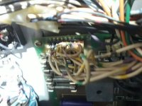
The board has arrived - so smart I photographed it! I went for the Xpin and it is an easy installation.
Except! I also ordered a Molex connector and tool to replace the original wires for GI soldered onto to CN8 plug. I cannot see an equivalent on the new board (xp-de5047). I shall attempt to power it up and sort out where I can connect the GI wires - about 4 or 5 I think.
(Sorry it is a bit vague - pinball is yet to be moved to the house and is in the lambing shed! I am about to go down there now in any case as last ewe looks like she is ready!)
 
Sussed it. Connectors had been renumbered. Pretty obvious when I thought about it!

Used new Molex connector, albeit a 11-pin version, for the original CN8 which was all GI. Noted that the original soldering was to the non-fused part but I connected them to the fused.

Powered up and it hums with Open Door. Tried that but the key fits and does not turn.

Any idea why it demands to open the coin door before lighting anything?
 
Oh, and twin lambs were born whilst I was wiring the Molex! Bet that does not happen often. Anyone remotely interested and I will post a photo tomorrow!

Thanks everyone for your help so far. My dear wife has no confidence in me sorting this pintable out. However the fella from Pinball Heaven may have been mistaken as I managed to get a sort of game on my old Sea Scare last night when he thought it would be only good for a skip having been stored in a cowshed for about 8 years!
 
Sussed it. Connectors had been renumbered. Pretty obvious when I thought about it!

Used new Molex connector, albeit a 11-pin version, for the original CN8 which was all GI. Noted that the original soldering was to the non-fused part but I connected them to the fused.

Powered up and it hums with Open Door. Tried that but the key fits and does not turn.

Any idea why it demands to open the coin door before lighting anything?
Normally means all the settings are lost, I believe.

Open the coin door and go through the menu and apply any settings you need/want to change. Or, I think you can open it and close it again and it will use default settings (may be wrong on this).
 
Possibly it’s wanting to tell you about faults which you need to access with the menu buttons inside the door. Try wd40 in lock then heat the key and jiggle using pliers. You need that door open as at the least you want to make sure the balls aren’t corroded as they’ll rip up the playfield in no time.
 
I won't be surprised if the settings were lost as I had to replace all the batteries on the CPU board. Completely dead, all of them.

I don't understand how the lock has jammed. The JP machine has been kept in a house for the last 7 years. Only been in the lambing shed for a few days. No sign of corrosion any where. (Unlike Sea Scare which has corrosion throughout.)

Twin lambs so I am knackered and off to bed. Thanks very much for all your help as I would have been lost on this system even now with a decent manual.
 
Waynj4 was correct! Opening and closing the door resulted in a message something like: "Please wait. Testing T-Rex"! I was rather over-the-bloody-moon with that!

By the way, I have drilled out a few locks in my time - being brought up in the South Wales valleys it is a necessary skill! - but I had to nigh-on drill the barrel out as the latch had jammed. I think I was given the correct keys but someone had a go at the lock. (Ended up with a crowbar holding the door ajar just enough I could hit the latch with a hammer and large screwdriver!)

I have made something a bit worse as there are no GI lamps now. This strongly suggests that the Molex connection I have made up has not worked at all but I will check the voltages tomorrow. There is something puzzling me though. This image shows that there seems to be a connection without an equivalent on the new Xpin board. I think that I must have pulled this one off the original board and missed photographing it. (It is in the foreground of the image and sorry it is out of focus.) I will look for an article for the pinouts on the Xpin board and combine that with the original manual schematic to work it out.


20210404_201147.jpg

Thanks again for your help so far. I think we are getting there! And it is a "we" as there is no way I could have done this without the help from this group of dedicated and kind people!
 
Oh, and mother and twins are doing fine! As there is lovely weather in the afternoons here, we put them onto a paddock adjacent to the house. It is funny to see the lambs looking around thinking "What on earth is all of this?" - well only seen the inside of their mother and a pen in a shed up to that point.
 
Having consulted Pinwiki - and if CN1 on the new board is the old CN8, I need to add the cables to the new connector. I shall check first for an Xpin schematic though.
 
811ba2ebad5873497da0543dd70e4d66.jpg

This is my original board from Tommy and I am struggling to make out that connector you have on the power board.

I though the yellow top wires and GI, hard wired on the old board and a yellow extender that connects from the board to the original GI connector.
 
Have to agree with @Jagspete on this one - just repinned the rats nest below on my LW3 today & the colours are right for the top half of CN8 (don't have pics of the 'after', but I do have a full set of GI again now for the first time since christmas)

1617581185645.png
 
I shall populate the next contacts with those cables and see what happens. Just tried to play it but it has lots of problems. No flippers and the gun thing does not fire a ball. Also shoved out two balls and something constantly tried actuating. I had better go through the diagnostics.
 
Yes - I used the same connections to the lower 9 joints on the new connector and now they mostly work - apart from a few blown bulbs. Or at least they did until I moved the machine from the lambing shed to the house. Now the lights in the top half of the back box do not illuminate. I dare say I can easily sort that one out compared to its other problems. (I was not sorry to get it from the shed. Bloody cold down there today, even for doing the connector!)

I just had my first ever attempt at the built-in diagnostics of a modern machine. I think that they are quite thorough if I could understand them. I can see that the kicker solenoid is not working too well so I will try to get back to the one which tests all the coils and note any with problems.

(By the way, I am loving this! Even though there are some "issues" preventing anything like a game being played, I am now hopeful that it is not a write-off!) There are many more coils, switches and lamps on these systems compared with the old 70's EM machines.
 
For the last few months, my spare time has been spent fixing and any playing is to test and I agree, there is a simple pleasure to troubleshooting and then repairing a machine.
 
I was expecting the coil tests to include the three flipper coils. Something else going on there, methinks. Something to do with the flipper PCBs.

I suspect the kicker to launch the ball is slightly broken as I can hear it trying but only just moves the ball.

A bit more progress though!
 
An update: Flippers are attempting to flip but I think with only the 8V supply. I tried to test one of the holes in the playfield (can't remember their official name) and it looks like it lost the ball. I found out that the damn thing is stuck at the bottom of a mini mine shaft! I correlated that with a status report about the Rt VUK (#5L). I suspect that is a vertical kicker.

The right VUK was also not responding when I tried the Coil Test. That took a bit of working out and I eventually realised that FH or similar means flasher relays and not solenoids. There is a Rasper Pit which I think supposed to fire the ball back out immediately. That is reporting a dead coil too. Jeez, how many coils are in these machines these days??

The other coil without any reaction is called Auto Launch 50V. I think that is the same as the usual launch initiated from the trigger and that does not work.

Tomorrow I will suss out how to test the 50V supply to the flippers as this new-fangled solid state thing will only stick 50V through the coils for a fraction of a second. I could quite easily diagnose the old flipper mechs where there were two coils.
 
With that many coils out/weak I’d think it’s more likely an issue with the mpu board- rather than lots of coils going. You could check and reseat all the connections on the board, think bottom ones and or right side are the coil drivers. ( the board with the batteries on) Pull them, check your pins aren’t corroded and reseat them
 
I found a common link between the unoperable coils: they are all 50VDC coils. I tested a fuse near the connector on the playfield power board and it just fell out of the holder. When trying to replace it, on of the holder's clamps snapped. I ended up cutting a fuseholder out of the old power supply board and soldering that on. Still no joy though. I will try to find a way of testing the 50V supply from its source.
 
No +50VDC coming from the playfield power board. That would explain it! My damn clever fuse thing needn't matter if there was no current to go through the fuse.

I wonder if that would explain the lack of flippers too.
 
I think the board is knackered as well as the main power supply. I went through the coil tests and when the knocker coil went all the backbox lights went out. I found this mess soldered onto the PPB board.

There is also no 50V coming from that board.
 

Attachments

  • 20210406_175342.jpg
    20210406_175342.jpg
    100.2 KB · Views: 17
Wow. This machine has some interesting previous work to keep it going.
My thoughts are that wiring must have worked to some degree as I assume the neighbour played it.
So what is causing the loss of 50v, you mentioned some solenoids were weakly firing so what was powering them?
Have you checked the bridge rectifiers?
If we didn’t share this before:
 
I think the board is knackered as well as the main power supply. I went through the coil tests and when the knocker coil went all the backbox lights went out. I found this mess soldered onto the PPB board.

There is also no 50V coming from that board.
Aha - that'll be the other end of the GI stuff that the extra wire you asked about before goes on - here's what mine looked like until I repinned it - at least now when I need to take out either the power board or PPB, there's no need to undo chocolate box connectors

1617735145550.png
 
@ger_marsh sorry to derail your thread mate (and I really dig your enthusiasm for pinball!!), but you gotta post a picture of the twin baby lambs - my daughter is asking 😇
Here's where I was attempting to sort out the electrical problem with the last expectant ewe alongside...20210402_211217.jpg

And here is the first just born....
20210402_221213.jpg

I shall photograph them in the field tomorrow. We keep them in the nice warm shed overnight!

In the meantime, here is a photo of triplets from last year:
_MG_2537.jpg

The breed is Zwartbles.
 
Back
Top Bottom