What's new
Pinball info

Register a free account today to become a member! Once signed in, you'll be able to participate on this site by adding your own topics and posts, as well as connect with other members through your own private inbox!

Jurassic Park (1990's version) not starting - Any ideas?

ger_marsh

Registered
Joined
Mar 25, 2021
Messages
43
Location
Carmarthen, South Wales
Hello to you all,

I am new here so please excuse my ignorance. I searched this forum but could find nothing like this problem.

Neighbour has asked me to look at a problem with a Jurassic Park pin which they have had for some time. I suspect it has not worked for some time too!

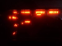
On starting up, most lights illuminate ok but the display only shows a strange pattern. There are no lit LED's on the CPU board too which I assume must be pretty fatal. This is what the display shows:
JP - DMD.jpg

There was a burnt out connector which was preventing half the backglass lights working but that was easily sorted with a connector block. Lots of current over lots of hours I suppose.

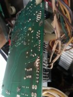
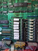
However, there is some scorching on the CPU board above a column of resistors:
JP CPU.jpg

I checked the resistors and they are all within tolerance.

The display controller had a very loose connection for 5V and Gnd and removing the connection completely resulted in the same display! (Actually, I should have checked the voltage on that - perhaps it is not working at all.)

Sorry for the quality of the images - old mobile phone!

If anyone has any ideas, I shall be grateful. I will check the voltages coming on the board today or tomorrow.

(I am new to the fully solid state machines - I fixed up my old EM machine quite easily and that was completely dead when I bought it.)
 
Hello
I am no expert but a fellow sufferer of Data East machine of a similar era. Mine is a Tommy which was made the following year.
These machines are similar and very different from the Williams games from the same period.

Other than the display not working, does the machine otherwise seem happy to start a game?
The burnt dust marks are common on that board so if everything checks out then do not worry for now.

As for the display, it could be a simple reseat of the cables, a power issue from the power board or an old and out gassed DMD.
This was the journey I was on recently. If you haven't already, try reseating the cables to see if that makes a difference. Both ends of the cable that goes from the CPU to the display board and then the cable from the display board to the DMD.
If that changes little, then the next thing is usually to swap over a known working DMD.
If that doesn't work then check the voltages from the power supply board to the display board. This page and whole site is very usefull.

https://www.pinwiki.com/wiki/index....-01_-_High_Voltage_Missing_at_the_DMD_display

Read the first bit and then take the readings at the pin going into the DMD. The pins going to the Displayv board are 5vdc and easy to test to but less likely to be the issue.
The drop between pin 1 & 2 should be >12v but that also seems to be dependant on the DMD, babcock's seemed to be more sensitive than cherrys.
Obviously, DANGER, DANGER, HIGH VOLTAGE so one hand in your pocket.

Good luck and let us know.
 
Missing 5v almost definitely.

MOST likely. There is a small capacitor below the bottom right of the large aluminium heat sink on the power supply. It most likely has leaked and you might well see the liquid contents on the circuit board around the capacitor. It will need replacing and the liquid cleaning up. This capacitor is crucial for 5v.
 
Thank you all for your prompt replies! Am I to assume that the 5V is missing for the entire machine or just the DMD. If there is no %V supply at all that would explain why the CPU does not wake up.

I am correct in thinking that Data East could have used better connectors for these boards? They seem a bit flimsy to me!
 
The enthusiasm in this forum is infectious. I am determined to get my own new pinball after I have sorted this one. Even if it means selling Sea Scare for room! Skills wise, I reckon I can replace capacitors, resistors and the like but my de-soldering is not up to integrated circuits. Nor is my ability to test them!
 
Missing 5v almost definitely.

MOST likely. There is a small capacitor below the bottom right of the large aluminium heat sink on the power supply. It most likely has leaked and you might well see the liquid contents on the circuit board around the capacitor. It will need replacing and the liquid cleaning up. This capacitor is crucial for 5v.
As there is no transformer I can see, I suppose it is below the playfield. I shall have to wait for the key to turn up!
 
Have you checked at the boards? That linked site should say where you are expecting 5v so you can confirm it. @pinballmania is rarely ever wrong in my experience.
Once narrowed down, you can decide if you want to replace or repair. I chose to buy a replacement as it wasn't a big cost for a board that takes a beating.

And yes, the hobby is infectious. You buy one, then need another and before you know it you need to build a log cabin to house them.
 
As there is no transformer I can see, I suppose it is below the playfield. I shall have to wait for the key to turn up!

I didn’t mention a transformer.
The power supply is the board at the top right. It has a large heat sink on it. With a circular transistor in the middle. The problem capacitor is on the board below the bottom right hand side of the heat sink.
 
Should that not be top Left for the power supply board?

Anyway, when you find it, I believe it should have a Test point (TP1) that should show the 5Vdc. Should be easy to check if it is there.
 
Wow! Thank you very much for the information so far! That Pinwiki resource is excellent for someone like me with a basic knowledge of electronics but not much of a clue how a modern(ish!) pinball machine works. I shall let you know how I get on.
 
Yes, the AA batteries supply memory to the SRAM when the machine is off to keep settings and high scores.
The biggest concern when a machine is left for a while is those batteries leak into important parts of the game. Off board batteries holders are a good idea or NVRAM replacing the SRAM.
 
Both 5v and 12v supplies are dead. C2 has definitely leakeD but has not damaged the track from what I can see. Does the lack of 12v suggest something else has gone? Also I note that some wires have been directly soldered ontosome pins. (Sorry for typing. In lambing shed!)
 
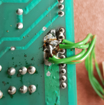
I assume that soldering some cables (which seem to go the the top of the backbox) into a plug on the power supply is not normal. Here they are:
20210326_155554.jpg

And the globule of solder at the back looks like I have done it!

A summary of what I have learnt about this generation of pins so far:
  1. The electronic design must have been interesting - especially for tables with non-standard features;
  2. Plugs and sockets have not improved much in their ability to carry some current for a long period;
  3. Solid state flipper drivers must have been quite pioneering at first but a brilliant idea and execution;
  4. I do not think they were intended to last this long!
Cracking engineering though. Fair play to the designers and manufacturers. I cannot imagine what my 13-year-old self would have thought encountering these instead of the like of Paddock and Magic City!

As you can probably tell, revitalised my love of pinball!
 
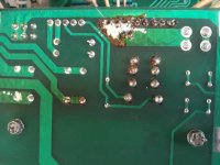
Are these scorch marks normal for a game of this age?...
20210326_152812.jpg

And this looks a bit of a mess too...
20210326_155745.jpg

I suspect that it may be a replacement for the entire power supply board. Are there any recommended suppliers in the UK?
 
Replacement was my conclusion for these power board that have been hacked and are so tired.
The xpin was recommended and was about two weeks back order from Phill at Pinball Heaven


Lovely board and has LEDs to show you the circuits are live and which fuses blown.
 
Replacement was my conclusion for these power board that have been hacked and are so tired.
The xpin was recommended and was about two weeks back order from Phill at Pinball Heaven


Lovely board and has LEDs to show you the circuits are live and which fuses blown.
I assume that "hacked" means modified hardware-wise. I do not know the history but the owner has never had anyone in to repair it. Even if I replaced the capacitors, I would have some trouble with soldering in the new ones. They are so tight to the PCB.

Thank you for your response, as ever.

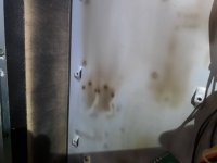
By the way, I think I will patent my mechanism for moving a pintable through a short distance!:
20210326_090643.jpg
 
I’ll second the xpin at around £150, but you’ll need to get a new connector as soldering wires to connectors not the thing to do. Also when starting up I’d attach one connector at a time in case there’s faults elsewhere , and keep my finger on the off switch
 
Are these scorch marks normal for a game of this age?...
View attachment 135728

And this looks a bit of a mess too...
View attachment 135729

I suspect that it may be a replacement for the entire power supply board. Are there any recommended suppliers in the UK?
Looks reminiscent of the power board in my LW3.

1616794401313.png

It's the GI so it can get fairly hot. On mine the other 4 pins have a connector rather than direct soldering, but it is very dark brown rather than white. I have just fixed a hack at the PPB end of the same by repinning the connector, so if I can get stuff checked out for continuity with mine, I'll try repinning that as well (it's kinda scary as I don't have much experience, but I think it's doable).
 
I recommend Molex for the connectors. Buy the crimp tool and pins and it is almost therapeutic.
My view is that if the board is going to be replaced anyway, then have a go at repairing it.
 
I recommend Molex for the connectors. Buy the crimp tool and pins and it is almost therapeutic.
My view is that if the board is going to be replaced anyway, then have a go at repairing it.
I agree - without the option of a replacement board, I'd be sending it away for someone else to do. I'll probably LED the GI to keep it cool in the future, even though I have gone trifurcon rather than IDC
 
There is an interesting thought LED the GI to keep it cool. Must remember to do this on my NF.
 
Personally, I'd start with desoldering the bodge wires and redo with proper crimp connectors. If you did decide to go down the route of a new PS Board, you'd still have to do this anyway.

Check all voltages from the start (where it comes to in to the board from the transformer), and work your way through the board from there.

I believe the square plugs on the Power supply board (CN1 & CN8?) can also get burnt up, so worth checking they're in a good state too.
 
That’s great, remember don’t power everything up at once, good luck, if you need photos of connectors just pipe up!
 
Back
Top Bottom