What's new
Pinball info

Register a free account today to become a member! Once signed in, you'll be able to participate on this site by adding your own topics and posts, as well as connect with other members through your own private inbox!

Jokerz A/C Relay Clicking, Specific Solenoids Inop? Help Required Please.

Right!... So after testing voltage on each side of F2A I found I was getting a reading on the left side of the fuse however none on the right. Realising the fuse I replaced yesterday was likely blown. I replaced it and turned the game back on. The "KE" flasher remained on however the ball eject spat two balls out. I ran a coil test below. Turned the game off and on again however on turning it back on I found fuse F2A blown again taking me back to my previous results.

Here is the link to the coil test video, with a working fuse...
VIDEO HERE
 
OK, please measure Q25 as described above (or cut it right out), replace the fuse and try again. Probably your culprit.
 
Yes, most definitely. And as written somewhere above, easy to test: buzz from the banded side of D32 to ground - if that has low resistance/buzzes you have found your issue. No need though as it is definitely broken - this is the reason why you get indiscriminate balls fed and the KE flasher blinking all the time. It may be something further up the line, you can identify by testing the TIP122 (<- Q25) as described above. It is very rare though that the final driver is whole and the control logic is busted.
 
Testing continuity of Q25 does give a beep however as stated testing the other transistors on the same row they do not. Seems fairly clear it is at fault.

Have some ordered, expected Friday. Will swap the transistor, replace fuse 2A and report back 👍🏻
 
You can just snip Q25 out, replace the fuse and see what happens. Lane feeder and "KE" won't work but you'll see if there is more.
 
I'm afraid that there is more. In the most recent video clip, the back-box wooden insert board seems to have some of the flashbulbs always lit - around the spinning wheel. They dim while some of the other solenoids operate. They should only flash when their turn comes around. 'Wheel Flashers' are Solenoid 11, listed as four bulbs on the insert.
 
Last edited:
I'm afraid that there is more. In the most recent video clip, the back-box wooden insert board seems to have some of the flashbulbs always lit - around the spinning wheel. They dim while some of the other solenoids operate. They should only flash when their turn comes around.
If that is the case Jay then I believe thats an issue that may have existed prior to my coil problem as I believe they've always operated in that manner since I got the table.
 
In my recollection, they're flashed while the wheel spins, as the machine says 'Draw Poker'. They certainly wouldn't be lit continually. In the coil test, when Solenoid 10, Playfield and Insert G.I. relay, operates, nothing should be lit on the insert, or playfield; the matrixed 'feature' lamps are shut off, the GI relay has broken the ac background lighting circuit, and no flashbulbs should be operating. The Wheel Flashers, Solenoid 11, are controlled by Cpu transistor Q 16.

If I may suggest, try things with the C side eliminated by removing F2C. This will disable 01C through to 08C. With a good fuse in F2A, see if any of the 4 solenoids it protects 'lock on' when the machine is switched on, exposing a damaged transistor. Most likely the ball feeder, solenoid 2, Q 25. If any do lock on, switch off, and break the circuit by detaching the return wire from the coil. After temporarily dealing with anything amiss, then see which of them (01A, 02A, 05A and 08A) work in the solenoid test.

You mention that the eject spat out two balls - if that was the ball feeder serving two balls into the shooter lane, then it seems to be pulsing, rather than simply locking on. Giving me hope for Q 25, though the behaviour of the 'C' load ('K/E' flashbulbs) suggests otherwise.
 
Last edited:
Ok, so latest update and I think it's good news. I snipped out Q25 as suggested, replaced the fuse F2A and started the table. Everything seems to be working apart from the obvious ball feeder and "KE" flasher which would make sense after eliminating Q25. Tested turning the table on and off and it hasn't blown the fuse again so hopefully Q25 was the cause of that also.

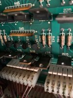
In regards to the draw poker flashers they do appear to be lit constantly. Checking the manual they're controlled by Q16. I've continuity tested Q16 and found I don't get a beep. It reads similar to the other transistors though as you can see below it does look as though it's gotten toasty at some point. I will replace this when I replace Q25.

IMG_2582.jpg

Feel as though I'm getting somewhere, thanks again for the wisdom! It's proving to be a good learning experience at the same time.
 
Please put your mulitmeter on diode test and look at Q16 with machine off, black lead on tab, measure to the outer legs. If you get anything other than .4-.6 V the transistor is shot.
 
Please put your mulitmeter on diode test and look at Q16 with machine off, black lead on tab, measure to the outer legs. If you get anything other than .4-.6 V the transistor is shot.
Thanks DrHex, once more please forgive my ignorance but black lead on "tab". Could you clarify where the "tab" is please?
 
Results are in. The leg on the left side gives a steady reading of 506 and the leg on the right gives a slightly fluctuating reading though very low 100's. Maybe 110. Would this reflect the theory that it's done for? Other transistors tested seem to show similar readings on each side. Certainly higher than low 100's.
 
Broken, please replace. In technical terms, these transistors are two diodes put together with their banded or non banded side in the middle. You're testing their pass through voltage. If that is lower than .4V the transistor is duff and needs replacing. You can cut Q16 out as well for now to save your flasher bulbs (do you have LEDs in there?), don't know if the machine is playable without the lane feeder solenoid though :).
 
Broken, please replace. In technical terms, these transistors are two diodes put together with their banded or non banded side in the middle. You're testing their pass through voltage. If that is lower than .4V the transistor is duff and needs replacing. You can cut Q16 out as well for now to save your flasher bulbs (do you have LEDs in there?), don't know if the machine is playable without the lane feeder solenoid though :).
Thanks for confirming and helping me diagnose. I have LED's in those spots at the moment. Replacements coming tomorrow or Friday. Hopefully this weekend it should all be back up and running. May cut it out anyway as I figure it might make it easier to remove when it comes to replacing.
 
A sited machine wouldn't be usable without the feeder working, but at home Jonathan could play it with the door open, operating the feeder manually. It's not as if this is a Dr. Who, or Johnny Moronic, which don't take kindly to having the door open, or that there's a courtesy switch for solenoid power.

A check of the feeder solenoid is wise, though. If it looks damaged, or shows a much lower resistance than a similar coil (23-800) then it will just repeat the whole thing again. If Q 25 was indeed shorted, the chances are that locking on the coil has overheated it, melting the lacquer insulation of the winding and short-circuiting it. Hence F2A blowing very quickly in post No.31, above.

There are also 'tie-back' diodes on all coil circuits, to prevent damage to driver (and other) components from solenoid pulses. They used to be attached to the coils themselves (they still are, for flipper coils), but Jokerz has all the others on the Aux Power board. A bit of sensibility has them numbered to tally with the solenoid drive, mostly anyway. The one for Solenoid 2 is D 2, and for Solenoid 11 it's D 11. These aren't the large diodes used for the A/C network, but smaller 1N 4003 devices. Shorted, they'd blow the fuse in their own right (if not worse, see a recent topic about a Robocop), but if one's open-circuit it wouldn't give any protection and by default could cause strange problems. A diode only conducts in one direction, towards the banded (-ve) end.

Looking at the picture of Q 16 and its surroundings, the circuit board does look a little warmed. The connecting header seems to be charred, too. That little group of Q 10 to 13 and Q 14 to 17 are four drive circuits, the smaller transistors switch the larger ones, which then conduct current and operate whatever's connected. The small transistors can also get damaged in cases like this, Q 12 here. The flat brown component SR 5 is a handy strip of miniature resistors, used to ensure the large transistor switches Off when not in use by connecting its controlling 'base' terminal to ground, Pin 1 of the strip, with the white dot marking.
 
Last edited:
The feeder solenoid looks to be clean and i'm certain it wasn't stuck on. Having said that I will test the resistance just to be sure.

I was more under the impression the short may have been caused by the flasher side of things with me replacing so many bulbs for LED's. That and after replacing them and turning it on the first ball ejected without issue. It wasn't until that first ball drained that I found problems. Leading me to think it may have been when flashers we're triggered during that first ball in play.
 
Now I don’t want to celebrate quite yet but I have replaced Q25 and Q16 tonight. Haven’t gotten to play a game as it’s late and my 4 month old is catching some z’s. However I have ran a coil test and everything is firing as and when it should.

Just wanted to extend my thanks to everyone that’s posted and given their input. Without the advice and knowledge base here I wouldn’t have felt anywhere near as confident enough to have given it a go. It’s been a great learning experience and won’t be put me off giving it another go if needed in the future.

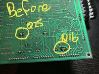
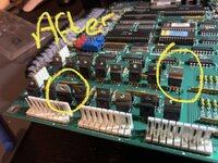
As for what I found… I removed the CPU board and it does look as though a couple of the transistors have been replaced in the past including both Q16 and Q25. I guess it’s possible those two higher rated fuses that were found (yes there was a second one) could have been in there for a while.

Here’s a couple of photos before and after for reference…
25AD5452-AFC9-4DDD-8102-147AEB88631C.jpeg

A166DA3F-F92C-47A7-B616-0B20A0154EFF.jpeg

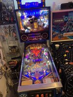
I’ll give a quick update tomorrow once I have a few games played but here it is back in one piece and looking shiny for the time being…

CE41C512-9A26-4F61-A677-DADF004F68AD.jpeg
B6F384E8-19D9-4204-9CB9-30136A5BAF4B.jpeg
 
Good news, let’s see how it fares. The higher fuse in itself doesn’t destroy anything, it just makes sure that whatever fails is thoroughly roasted (potentially incl your house…).
 
Afternoon guys, I promised some days ago now that I would give an update after playing a few games.

There is good news and bad. The game is fully playable though the issue I had previously with the rotating card wheel lights has returned. They're not stuck on but rather the opposite. They no longer seem to light at all.

I performed the initial solenoid/coil test after replacing both Q16 and Q25 and reported all was working. Sadly after the first game it appeared those LED's I have in place on the card wheel are no longer lighting.

I need to do some further investigation to see if I can determine where the fault may be though I've ruled out the fuse for these lights as the same fuse is connected to other parts of the table which are functioning ok.

It's not a deal breaker as it doesn't stop me from playing the game however it doesn't half bug me knowing it's not quite right.
 
OK, same process as before - measure for 25V at the flashers on the backboard (they should be there all the time as this isn't multiplexed like the ones failing earlier), i.e. put one lead of your multimeter on ground and the other one on the wires on the flashers. This should show 25V. Provided that is there, switch off the machine and buzz the cable from the flashers to Q16. If that is OK Q16 probably gave up the ghost or your soldering has a problem.
 
The flashbulb circuits drive what are basically car tail-lamp bulbs (as original fitment, anyway) using 25v power, ensuring they're bright. In order not to blow up the bulbs after just a few uses, there are ceramic high-wattage resistors used in the circuits. The particular value depends on how many lamps there are in any one circuit. By the time Jokerz was built, the resistors were grouped together on the 'Interconnect' board below the Cpu board. Look at the schematics to find which of the resistors is used for the Wheel flashers, Solenoid 11. The resistors were notorious for breakage while they were fitted on the playfield itself, though not so much afterwards. But if that circuit was locked on for a good while and was using bulbs at the time, the resistor could've overheated.

Edit - Looking at the manual, the schematic for the Interconnect has Solenoid 11 passing through connectors (2) J4, Pin 12, and connectors (2) J 11 for the Backbox Insert panel and J 12 for the playfield. For Jokerz, the backbox connection is used, but for both of them it's pin 5. An outbreak of sensibility has the resistor as R 11.

There's a conflict in the manual, which isn't unusual. The board-by-board listing at the back says Solenoid 11 is 2 J4 pin 14, but the schematic shows it as pin 12. Similarly, the backbox and playfield connectors are listed as J 11 & 12, pins 6, rather than 5. Watch out which is which on the actual machine.

The component listing for the Interconnect board doesn't seem to show the individual flashbulb resistor values, I'm afraid.
 
Last edited:
Back
Top Bottom